Describe the Use and Storage of Meters
I
Use and Storage of Multimeters
A technician is only as accurate as the measurement equipment they are using. If the equipment is used incorrectly or is faulty, then the measurements will be inaccurate. If the measurements are inaccurate, then the technician will draw the wrong conclusions. To avoid getting inaccurate readings, you need to handle, use, and store meters properly. When you are done using a multimeter, it should always be turned off to extend battery life.
Precautions in Handling and Using a Meter
These precautions apply equally to digital and analog meters.
- Do not drop any meter.
- Do not overload any meter. When in doubt, use a high range that you know will not be overloaded. You can always switch to a lower range if necessary.
- Do not tamper with precision instruments. Let a competent instrument repair person service precision instruments.
- Before you connect a meter to a circuit, ensure that the range switch is set to an appropriate position.
- Carefully check circuit connections before applying power to meters.
- Be careful not to touch any other electronic components within the equipment.
- Be careful not to touch the probe tips to each other while connected to anything else.
- Never switch settings (voltage to current for example) while the probes are connected to circuit
The two major types of meters are analog and digital (Figure 1). Although both meters perform the same functions, they look different.
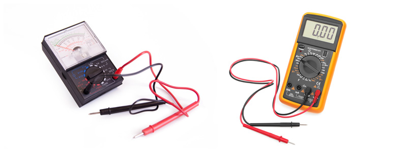 Figure 1: Analog multimeter and digital multimeter
As you can see, the difference is in the display unit. Digital meters are usually simpler to use and are more accurate than analog meters, and therefore have become more popular. We will focus on the digital multimeter (DMM), as it is the most common type in use, although analog multimeters may still be preferable in some cases, for example when monitoring a rapidly varying value.
Handling a Multimeter
 When handling a multimeter it is wise to be sure the meter is held securely. Dropping a multimeter, especially an analog meter, even from a small height can affect future readings and the accuracy of the multimeter. While taking readings the user is most likely going to need the use of both hands to complete the task. As a result it is necessary to be sure the meter is set securely in a safe place where it can be read without having to change the user’s position. If no suitable spot is available, a second person to hold the meter and/or record the readings may be necessary. Some meters also can be equipped with magnetic straps or tethers to aid in their use by a single technician.
Storage
Multimeters should be stored in a dry place where they will not be subject to physical damage. Most multimeters will come with a case in which to store them. This case not only keeps all the pieces together in one place (meter, leads, batteries, magnetic strap etc.) it will also protect the vulnerable parts, such as the display, from any damage that may occur.
When storing a multimeter for a prolonged period, removing the batteries will ensure that corrosion will not accumulate at the battery connections.
The leads on multimeters can be varying in length. Additional care must be taken to ensure the internal connections of the leads do not become damaged by tightly winding them around themselves.
Even though you may normally deal with small voltages and currents, the values are never far away from lethal levels. You can receive a shock or burn from any common electrical circuit. The severity of the electrical shock depends on a number of factors:
- The amount of current that passes through the body
- The path that the current takes through the body
- Type of voltage—AC or DC
- Voltage strength
- The surrounding environment (dry vs. moist, wet or damp)
- The length of time that the current flows within the body
- Condition of the skin and the body’s chemical makeup
- Area of contact
- The surrounding environment:
- Special care should be taken when considering your surrounding environment. Are you indoors? Are you exposed to the elements? Is there surrounding circuitry that may still be “live”. What’s going on around you? Is there a storm going on outside? This could result in high electrical transients on the equipment being tested. This surge could exceed the rating of the meter being used possibly resulting in a dangerous arc flash or arc blast. Are you testing in a hazardous location? If so this might mean a specialized meter, such as an intrinsically safe meter and specialized training may be required. All of these factors should be considered while testing with a multimeter as they may affect how safe you actually are.
Normal household currents (plugs and light circuits) are generally limited by a circuit breaker to a value of 15 amperes. This device has been designed to trip and open a circuit if the 15 ampere value is exceeded. It is designed to protect against property damage and not necessarily personal injury. The possibility of causing a fatal injury can occur with a current flow of only 50 milliamperes (mA) or five one-hundredths of an ampere (.05A). The body is sensitive to relatively small values of current. In comparison, a 100-watt lightbulb draws approximately 0.85 ampere (850 mA) of current when connected to a 120 volt source. Remember, there are 15 amperes available in each standard house circuit. Electrical shocks, electrical burns, and other related injuries occur far too often and in most instances, go unrecorded. If you come across someone who you think has received or is receiving an electrical shock, always keep in mind:
- Don’t touch the person and don’t use a conductive tool to free the person that may be electrically energized.
- Shut off the power or pull the plug if it is safe to do so. If you are not able to, go for help.
- Remove the person from the contact point using a non-conductive object such as a dry piece of wood or a leather belt.
- Call 911 for help if the person is obviously injured (loss of consciousness, significant trauma, etc.)
- Seek medical attention (first aid) in any case of injury such as an altered mental state (confusion, slow/slurred speech) or other obvious injury (laceration, burn, etc.). When performing maintenance or doing repair work, or when a machine is in an unsafe state, perform lock out/tag out procedures in conjunction with the T3 testing method and approved safety glasses and voltage rated gloves must be used.
T3 testing method
- T1-test a known live circuit with a meter or non-contact voltage tester.
- T2-test the device or circuit you plan to work on to ensure it’s “dead” or de-energized.
- T3-re-test the known live circuit to ensure the testing device being used (meter or non-contact tester) is still working as it should and has not been damaged by T2.
It is vital to eliminate the possibility of the machine being energized unexpectedly. In order to create a safe work environment, workers need to guard against contact with electrical voltages and control electrical currents by de-energizing the circuits providing power to the equipment you will be working with.
Make the environment safer by doing the following:
 Always wear the approved and appropriate personal protective equipment (PPE): safety glasses, voltage rated rubber gloves with leather protectors and nonflammable clothing, etc.
- Using the T3 testing method.
- Protect portable electrical equipment with an approved ground-fault circuit interrupter (GFI) when using the equipment outdoors.
- Ensure all the cords are in good condition, with the caps and plugs well secured on the cables. Ensure the proper U-ground plug is in good working condition.
- Use cords of sufficient gauge for the amount of current used by the tools they are powering. Each tool is labelled with the power that it draws.
- Treat all conductors and bare wires—even apparently de-energized ones—as if they are energized until they are proven otherwise by using lock out/ tag out procedures and the T3 method.
- Do not make any electrical measurements without specific instructions from a qualified person.
- When servicing equipment be sure it is “locked out,” meaning the electrical service is shut off at a disconnect panel whenever possible, the panel is locked, and the only key is kept by the person working on the equipment.
- When replacing components on mobile equipment, disconnect the battery.
Video: Lockout/Tag Out Procedure

A YouTube element has been excluded from this version of the text. You can view it online here: https://ecampusontario.pressbooks.pub/multimeters101/?p=29
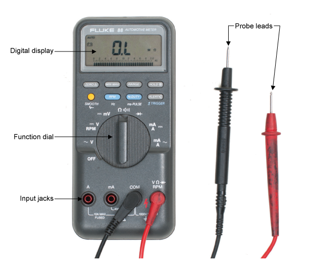
All digital multimeters combine the features of an ammeter, a voltmeter, and an ohmmeter. Figure 1 shows a typical DMM, although different makes and models may have a different number of digits in the display unit and the input/output jacks may be in slightly different positions. Since a DMM is an important tool, you will want to learn how to use one correctly.
Figure 2 – Typical Digital Multimeter
The upper portion of the DMM houses the display unit. The middle portion of the DMM houses the function switch, and the bottom portion contains the jacks for test leads.
The function switch normally has positions that will allow a technician to measure:
- AC/DC Volts (V)
- AC/DC Amps (A)
- Resistance Ohms (Ω)
In addition, some DMMs have function switch positions that will allow a technician to measure and to test diodes and capacitors. Some DMMs require manual setting of ranges; others have an auto ranging feature.
All DMMs may be used to measure voltage, current, and resistance. More advanced DMMs may measure frequency, relative power differences, or other important circuit parameters. Each measurement function has similarities and differences that you need to learn about.
Many meters will use symbols on the display, switch, and connections. Figure 2 lists some of the common symbols you may see.
Figure 2 – Common Symbols
 |
AC |
 |
DC |
| Ω |
Ohms |
 |
AC or DC |
| Hz |
Hertz |
| + |
Positive |
| – |
Negative |
| µF |
MicroFarad |
| m |
Milli |
| M |
mega |
 |
Low battery |
 |
Manual range or automatic touch hold |
 |
Continuity beeper |
 |
Diode |
 |
Ground |
 |
Fuse |
 |
Double insulation |
 |
Capacitor |
| OL |
Overload |
Introduction to Voltage Measurements
Voltage measurements are very easy to make with a DMM. On meters with manual range selection, start with a value one setting higher than expected. An auto range DMM will automatically select the range based on the voltage present. Figure 1 shows the process.
Note:
1/1000V = 1mV
1000 V = 1 kV
Figure 1 – Using a Digital Multimeter to Measure Voltage
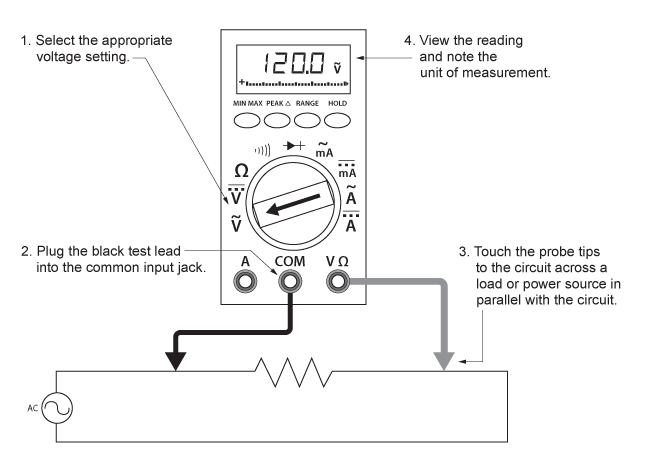
Follow these steps to measure voltage:
- Wearing the appropriate PPE: safety glasses, voltage rated rubber gloves with leather protectors and nonflammable clothing, etc.
- Select the appropriate voltage setting, A/C or D/C.
- Plug the test probes into the appropriate probe jacks, Common and V.
- Connect the tips of the probes across the source or load.
- View the reading on the display unit. Be sure to note the unit of measurement. If you are testing DC voltage and a negative sign appears in the display, the polarity of your probes is incorrect and needs to be reversed.
- Turn the meter off when testing is complete. This will prolong battery life.
Auto ranging units display the unit of measurement in the top right corner. In manual ranging units, the meter will use the range selected. Auto range will determine the highest setting and automatically display that unit.
Introduction to Current Measurements
As you have seen, the procedure for voltage measurements is relatively straightforward. The leads are simply connected across, or are parallel with, the points of voltage to be measured.
For current measurements, however, the process is slightly more complex. First, the circuit must be opened at the test points and the meter inserted in series at that opening (Figure 5). The total current must flow through the meter. To allow the measurement to be made without disturbing the circuit itself, the current meter has very little internal resistance.
This is where an inexperienced technician must be particularly alert. If the meter is inadvertently connected across a point of P.D. (potential difference) or in parallel with a component instead of in series, the small internal resistance will permit a very large current to flow through the meter resulting in a short circuit. This will most certainly damage the meter severely and perhaps the circuit as well. More alarming is the possibility of causing a dangerous arc flash. The severity of an arc flash depends on a number of factors including but not limited to the distance from the arc flash, the safety equipment worn or more specifically the lack of, the duration of the arc flash as well as the length of the arc flash. For more information on arc flash safety visit www.esasafe.com.
With current measurements, shutting off the power before connecting the meter is essential. You will be disconnecting one end of a wire or component to connect the meter in series. If you leave the power on, you could easily receive a dangerous shock or damage the circuit.
On meters with manual range selection, start with the highest current setting and work your way down.
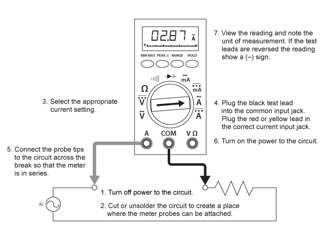
Figure 5 – Using a Digital Multimeter to Measure Current
Current Measurement Procedures
Follow the steps below to measure current in circuits of 0-30V:
- Before testing begins the technician should always know what reading to expect based on the manufactures specifications, name plate rating, Ohms’s law and Kirchhoffs law. Testing blindly is dangerous and counterproductive.
- Turn off the power and prove the circuit to be measured is “dead” using the T3 testing method and the voltage measuring procedures. Be sure to wear your PPE as we always assume a circuit is “live” until proven otherwise
- Open the circuit by disconnecting or unsoldering a connection at a point where you wish to measure current.
- Select the DC or AC amps function by turning the function switch to DC or AC amps.
- Plug the test leads into the appropriate jacks, black lead into the Common jack and the red lead in to the A or mA jack. Remember that you already have an expected value in mind this expected value will determine which jack, A or mA, will be used. 1/1000 A= 1 mA.
Note that the jacks used will not be the same ones used to measure voltage.
- Connect the tips of the probes across the break in the circuit as shown in Figure 6 so that the current to be measured flows through the meter. Note that this is a series connection. Never connect the ammeter in parallel with the source or load, as this will cause a short circuit and damage the meter and possibly a dangerous arc flash.
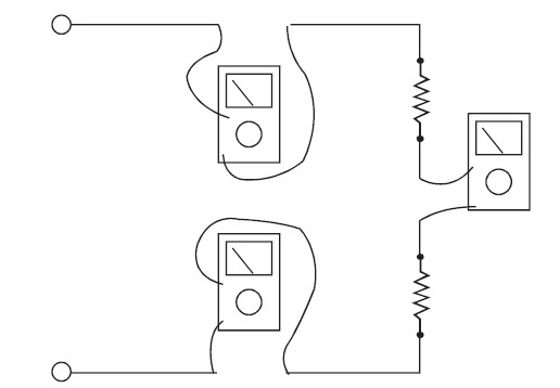
Figure 6: Ammeter connections to measure the same current at different points in a circuit
- Turn the circuit power back on.
- View the reading on the display unit. Be sure to note the unit of measurement.
- Switch power off again, once again proving with the T3 method while wearing your PPE.
- Disconnect meter leads from the circuit.
- If testing is finished at this test point, restore the circuit by reclosing the connection. When current measurements are complete, turn the function switch to the “OFF” position and remove the test leads.
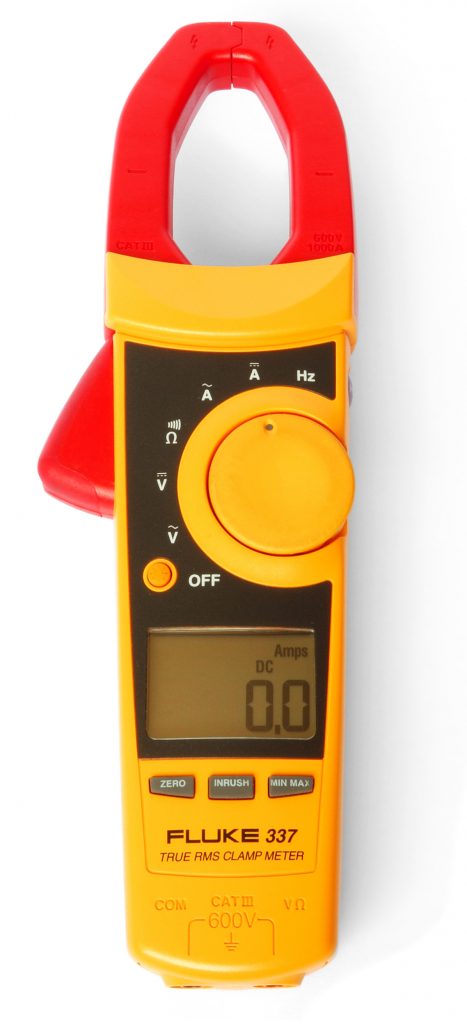
When measuring current on circuits with voltage values greater than 30 V or where “breaking” the circuit is impractical or dangerous, a clamp-on ammeter or amprobe can be used. These ammeters have two spring-loaded expandable jaws that allow you to clamp around a single conductor (Figure 7). This feature allows you to measure the magnetic field created by the current flowing through the wire to give an ampere reading without having to make physical contact or interfering with the circuit.
Figure 7: Clamp on Multimeter
Video: Current Measurement

A YouTube element has been excluded from this version of the text. You can view it online here: https://ecampusontario.pressbooks.pub/multimeters101/?p=38
Introduction to Resistance Measurements
You have studied voltage and current measurements, but you will find resistance measurements different in several ways. Resistance is measured with the circuit’s power turned off. The ohmmeter sends its own current through the unknown resistance and then measures that current to provide a resistance value readout.
Role of the Battery
Even though it reads out resistance, the ohmmeter is still a current-measuring device at heart. The ohmmeter is created from a DC current meter by the addition of a group of resistors (called multiplier resistors) and an internal battery. The battery supplies the current flow that is eventually measured by the meter. For this reason, use an ohmmeter only on de-energized circuits.
In the process of measuring resistance, the test leads are inserted in the meter jacks. The leads are then attached to the ends of whatever resistance is to be measured. Since current can flow either way through a pure resistance, there is no polarity requirement for attaching the meter leads. The meter’s battery sends a current flow through the unknown resistance, the meter’s internal resistors, and the current meter.
The ohmmeter is designed so that it will display 0 Ω when the test leads are clipped together (zero external resistance). The meter reads infinite (I) resistance or over limit (OL) resistance when the leads are left open. When a resistance is placed between the leads, the readout increases according to how much current that resistance allows to flow.
To conserve its battery, an ohmmeter should never be left on the ohms function when not in use. Since the current available from the meter depends on the state of charge of the battery, the DMM should be zero adjusted to start. This may require no more than a test of touching the two probes together.
Figure 8 shows how resistance measurements are taken.
Note:
1000 Ω = 1 kΩ
1 000 000 Ω = 1 MΩ
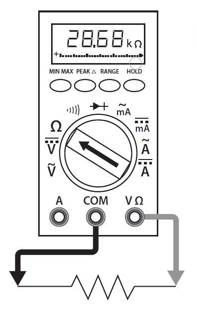
Figure 8: Using a DMM to Measure Resistance
- Turn off power to circuit.
- Plug the black test lead into the common input jack. Plug the red or yellow lead into the resistance input jack.
- Select the resistance setting.
- Touch the probe tips across the component or portion of the circuit.
- View the reading and note the unit of measurement, ohms, kilohms, or megohms.
Resistance Measurement Procedures
Follow the steps below to measure resistance:
- Before testing begins the technician should always know what reading to expect based on the manufactures specifications, name plate rating, Ohms’s law and Kirchhoffs law. Testing blindly is dangerous and counterproductive.
- Turn off the power and prove the circuit to be measured is “dead” using the T3 testing method and the voltage measuring procedures. Be sure to wear your PPE as we always assume a circuit is “live” until proven otherwise
- Remove or isolate the component to be tested.
- Plug the test probes into the appropriate probe jacks, Common and Ω. Note that the jacks used may be the same ones used to measure volts.
- Select the ohms function by turning the function switch to ohms. Start with the lowest setting.
- Touch the probes together to check the leads, connections and battery life. The meter should display zero or a very small amount of resistance for the test leads. With the leads apart, the meter should display OL or I, depending on the manufacturer.
- Connect the tips of the probes across the break in the component or portion of the circuit for which you want to determine resistance. If you get an OL (over limit), switch to the next highest setting.
- View the reading on the display unit. Be sure to note the unit of measurement.
- Turn the meter off when testing is complete to prolong battery life.
Video: Measuring Resistance

A YouTube element has been excluded from this version of the text. You can view it online here: https://ecampusontario.pressbooks.pub/multimeters101/?p=40
Introduction to Continuity Measurements
You can use the same connection procedure used in measuring current to verify that a circuit, wire, fuse, or switch is complete without breaks in the circuit. This is called a continuity test, and most DMMs will have an audible continuity setting (). If there is no audible alarm, then the circuit is broken. You can test the audible setting by touching the leads together while the leads are inserted into the common and continuity () jacks. A good example is testing a heating element when you suspect the heating element might be “burned out”. If the heating element is complete without breaks, the audible sound will ring out when tested. However it is important to note that the portion of the circuit to be measured needs to be isolated to ensure a false reading is not obtained. Failure to do so can mean that other parts of the circuit may be read inadvertently thus providing an inaccurate reading.
Use Meters to Analyze Simple Circuits
II
The trick to effectively troubleshooting electrical equipment and circuits is to zero in as quickly as possible on the problem. Using a multi meter will allow you to effectively test the components that are most likely causing of the problem before you unnecessarily dismantle the equipment and replace parts.
Troubleshooting Principles
1
There are really only two rules for troubleshooting using a voltmeter. They are simple and always true:
- If you measure a voltage across a switch, the switch is open.
- If you measure a correct voltage across a load and the load doesn’t work, the load has failed.
With digital meters, voltage readings that are considered as zero will often indicate very small voltage readings. For example, when reading across a closed switch, a very small reading could indicate a very slight resistance across the switch contacts or even a meter inaccuracy.
Notice that the first rule does not say that if you read zero volts across a switch, the switch is closed. There are many situations in which you might read zero volts across an open switch.
The second rule indicates that the load has failed. This only means that the problem is with the load and you don’t have to look anywhere else for the problem. The actual remedy still has to be determined. This may require a replacement of the load, but there may be other possibilities. For example, there may be an overload that needs resetting.
Always look for the easy fix first. Check components that are easily accessible first that might explain the symptom that you have observed. For example, one of the first checks is to verify the power supply.
You can troubleshoot a problem using either a volt or ohms test. It is most practical to choose voltage testing. With a resistance test, you have to first disconnect the component being tested from the circuit, and while you are removing the wiring you could jostle things and possibly change the circuit, which may temporarily remedy the problem. In other words, you may not really find the problem.
When you use your voltmeter to troubleshoot, you will find either a switch that is open or a load that has failed. You can do this without moving any wires and without changing the circuit in any way. You may then remove the device and double check it with your ohmmeter.
Voltage Drops in Series Circuits
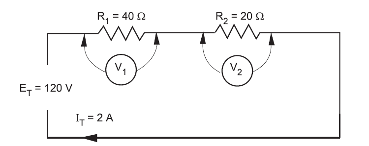
In series circuits, the total voltage is the sum of the individual voltage drops in the circuit, and the equation E = IR is used to calculate the voltage drop across each resistor. Since the current is the same through each resistor, the voltage drop across each resistor is directly proportional to the value of resistance. In other words, the greater the value of a resistor in a series circuit, the higher the voltage drop. Consider the simple series circuit in Figure 1.
Figure 1 – Series Circuit
From the values given above, you can easily calculate the voltage drop across each resistor by:
E1 = I1 × R1 = 2 A × 40 Ω = 80 V
E2 = I2 × R2 = 2 A × 20 Ω = 40 V
The voltage drop of 80 V across the 40 Ω resistor is twice the voltage drop across the 20 Ω resistor.
Refer to Figure 2. If an open is introduced between resistors R1 and R2 (for example, by disconnecting a lead), current flow through the circuit is, of course, interrupted. If there is no current flow, the voltage drop across each of the resistive elements is zero (since E = I × R).
However, the potential difference of the source still exists across the open. If a voltmeter is connected across the open, the reading is the same as if it were connected directly across the terminals of the supply source.
Figure 2 – Voltage Across and Open Circuit
In a series lighting circuit, you could easily determine which lamp was burnt open simply by measuring the voltage across the lamp-holder terminals, in succession, until you have measured the total source voltage.
Caution! Since the source voltage still exists across the opening in a series circuit, this represents a shock hazard. Be careful not to touch the live parts of the circuit! Similarly, if a switch is opened, the full-source voltage will appear across the switch contacts. Even though the voltage across the load devices may be zero, if any of those loads are ahead of the switch they will be energized with full voltage to the ground.
Troubleshooting Series Components
3
Sometimes you will be required to troubleshoot a piece of equipment that has stopped working. The first thing you would check for is power. Is the breaker off? Is the switch off? Is there a general power outage?
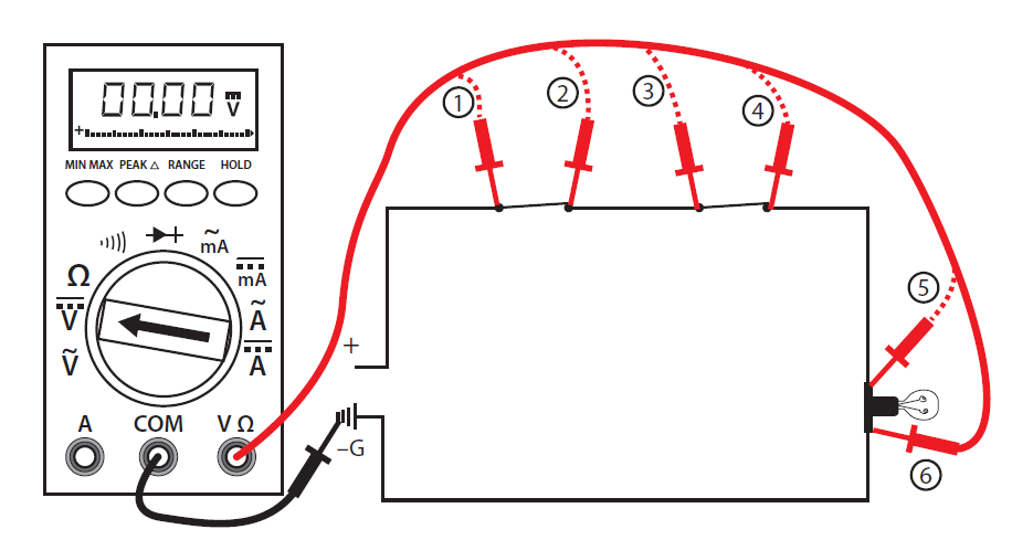
Once you have determined that power is still available you can begin using the multimeter to locate the problem. Starting with the first component or the one easiest to check, work your way through the circuit until you reach the component that shows no voltage reading. This is known as hopscotch voltage readings. Figure 3 illustrates this process. The dashed line indicates where the probe has already been placed and removed.
Figure 3: Hopscotch Troubleshooting
Follow these steps to complete the voltage test procedures with an autorange meter:
- Set the selector dial to the type of current to be tested: AC or DC.
- Once you have determined that the load (shown as a lightbulb) is not working, check for voltage across the light first to verify rule #2 (i.e., if you measure a correct voltage across a load and the load doesn’t work, the load has failed.).
- If you have voltage across the light, then the light has failed. If there are zero volts across the light, then one of the switches or wiring connections in the circuit has failed. If you have a zero reading across the light, continue with the next steps.
- Place the black probe at a grounded component.
- Place the red probe and check for a voltage reading at each test point in order starting at test point 1, verifying power supply.
- Continue working your way through the circuit until you get a zero reading, which would indicate a break in the circuit just before that point.
- Reading at 2 = switch #1 closed, zero at 2 = switch #1 open
- Reading at 3 = wiring to switch #2 good, zero at 3 = wiring to switch #2 open
- Reading at 4 = switch #2 closed, zero at 4 = switch #2 open
- Reading at 5 = wiring to light good, zero at 5 = wiring to light open
- Reading at 6 = load is energized, zero at 6 = the load is open (although you have already checked the load in your first test). If you get to this stage and the load is energized, the only component left that must be faulty is the final wiring from the load to ground.
- Once the open in the circuit has been identified, you can de-energize the circuit, remove the component, and double check the component with your ohmmeter.
- If this is the last test you are doing, turn the meter to “off” and store in a safe place.
Note: There may be other circuits that are energized even though the circuit you are working on is not energized. DO NOT TOUCH THE METER PROBES TO ANY ENERGIZED COMPONENTS WHEN TESTING FOR Ω (RESISTANCE). YOU MAY DAMAGE THE METER.
Video: Troubleshooting Series Circuits

A YouTube element has been excluded from this version of the text. You can view it online here: https://ecampusontario.pressbooks.pub/multimeters101/?p=99
Testing Resistance (Ohms) with a Digital Multimeter
4
This test, using a digital multimeter, determines whether:
- an electrical circuit is complete or broken
- the resistance of a component matches the manufacturer’s specification
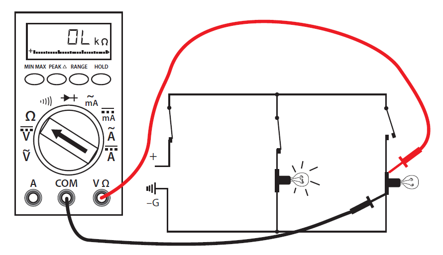
Figure 4: Ohm Test of a Load
Follow these steps to complete the resistance test procedure:
- Make sure all power is off on the circuit you are testing.
- Make sure that the component that you are testing is isolated from the complete circuit. Either remove the component from the circuit or isolate it with an open switch.
- Set the selector dial to Ω.
- Connect the test lead and probes to the component terminals as shown (Figure 4).
- Observe the readout window to obtain the Ω reading.
- Compare the results to the manufacturer’s Ω specifications. If the readings match the component, then resistance is not a problem. If the component is a load, there should be resistance that matches the manufacturer’s specs.
- If the reading is infinite (I) or overloaded (OL), then the component is open.
- If the reading is zero, then the component is closed (if it is a load then this is an internal short).
- If this is the last test you are doing, turn the meter to “off” and store it in a safe place.
Video: Testing Resistance
A YouTube element has been excluded from this version of the text. You can view it online here: https://ecampusontario.pressbooks.pub/multimeters101/?p=102
There may be other circuits that are energized even though the circuit you are working on is not energized. DO NOT TOUCH THE METER PROBES TO ANY ENERGIZED COMPONENTS WHEN TESTING FOR CONTINUITY. YOU MAY DAMAGE THE METER.
This is a quick audible alarm test using a digital multimeter to determine whether an electrical circuit or wire is complete or broken.
This test can be applied to a circuit as a whole or in sections—on individual components or sections of wiring. A break in continuity can be caused by mechanical damage, corrosion of components, or simply a switch being left open.
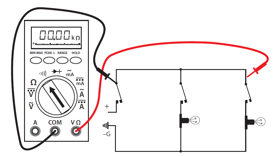
Follow these steps to complete the continuity test procedure with an autorange digital meter:
- Make sure all power is off in the circuit you are testing.
- Set the selector dial to Ω (audible alarm symbol).
- Connect the test lead and probes on the load terminals as shown (Figure 5). The audible alarm will indicate continuity without a need for taking your eyes off the work.
- Touch the probes together to check the leads, connections, and battery life. The audible alarm should sound. With the leads apart the meter should display OL or I, depending on the manufacturer.
- If this is the last test you are doing, turn the meter to “off” and store it in a safe place.
Figure 5: Wiring for a Continuity Test
Polarity in a Parallel Circuit
6
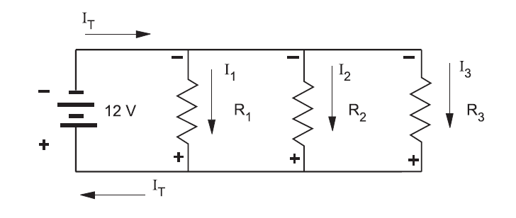
Just as in series circuits, electrical current flows “from negative to positive” through each of the load components in a parallel circuit. As illustrated in Figure 6, electrons leave the negative terminal of the source and flow from negative to positive through each of the load resistors. Note that the polarity of each of the resistors is the same as the polarity of the source.
Figure 6 – Polarity in a Parallel Circuit
Polarity is always expressed from one point of a circuit relative to another point with a different electrical potential. Note that in Figure 6 the top side of each resistor, which is marked negative, is in effect the same point. No difference in potential exists between any of these like terminals.
Also notice that the individual currents through each resistor (I1, I2, I3) together constitute the total current (IT) drawn from the source. When the total current required to operate each of these parallel loads exceeds the current output rating of the one source, you will need to increase the source output.
Polarity Test for Parallel Voltage Sources
Voltage sources are connected in parallel whenever it is necessary to deliver a current output greater than the current output a single source of supply can provide, without increasing voltage across a load.
- Power sources are connected in series to increase the voltage output.
- Conversely, power sources are connected in parallel to increase the current capacity.
An advantage of parallel-connected power sources is that one source can be removed for maintenance or repairs while reduced power to the load is maintained. If a 6 V battery has a maximum current output of 1 A, and if it is necessary to supply a load requiring 2 A, then you can connect a second 6 V battery in parallel with the first.
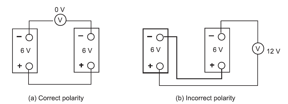
If there is any doubt about the polarity of the two batteries, then you can do a simple voltmeter test for correct polarity.
- Tie one side of the power sources together.
- Before connecting the paralleling jumper between the remaining two terminals, insert a voltmeter between these two points. See Figure 7.
- If the polarity is incorrect (Figure 7b), the voltmeter indicates two times the source voltage, because the equal EMFs aid each other. Do NOT connect across these terminals.
CAUTION! Since there is a difference in potential between these two points, connecting a paralleling jumper between them would result in a short circuit!
If the polarity is correct (Figure 7a), then the voltmeter indicates 0 V because the EMFs oppose each other. You may connect a paralleling jumper between these two points.
Figure 7: Polarity Test