Pattern Development: Sheet Metal Level 1
Pattern Development: Sheet Metal Level 1
Line E
Brian Coey
BCcampus
Victoria, B.C.
© 2021 Brian Coey
The CC licence permits you to retain, reuse, copy, redistribute, and revise this book—in whole or in part—for free providing the author is attributed as follows:
If you redistribute all or part of this book, it is recommended the following statement be added to the copyright page so readers can access the original book at no cost:
Sample APA-style citation (7th Edition):
Coey, B. (2021). Pattern Development: Sheet Metal Level 1. BCcampus. https://opentextbc.ca/patterndevelopment/
Image attributions:
All GIFs and images in this book are © Camosun College and licensed under a
CC BY 4.0 Licence, unless otherwise noted.
Cover image attribution:
“
Right Cone – Step 8” by Camosun College is licensed under a
CC BY 4.0 Licence.
Ebook ISBN: 978-1-77420-124-4
Print ISBN: 978-1-77420-123-7
Visit BCcampus Open Education to learn about open education in British Columbia.
1
Accessibility Statement
BCcampus Open Education believes that education must be available to everyone. This means supporting the creation of free, open, and accessible educational resources. We are actively committed to increasing the accessibility and usability of the textbooks we produce.
Accessibility of This Textbook
Accessibility Checklist | Element | Requirements | Pass? |
|---|
| Headings | Content is organized under headings and subheadings that are used sequentially. | Yes |
|---|
| Images | Images that convey information include alternative text descriptions. These descriptions are provided in the alt text field, in the surrounding text, or linked to as a long description. | No |
|---|
| Images | Images and text do not rely on colour to convey information. | Yes |
|---|
| Images | Images that are purely decorative or are already described in the surrounding text contain empty alternative text descriptions. (Descriptive text is unnecessary if the image doesn’t convey contextual content information.) | Yes |
|---|
| Tables | Tables include row and/or column headers that have the correct scope assigned. | N/A |
|---|
| Tables | Tables include a title or caption. | N/A |
|---|
| Tables | Tables do not have merged or split cells. | N/A |
|---|
| Tables | Tables have adequate cell padding. | N/A |
|---|
| Links | The link text describes the destination of the link. | Yes |
|---|
| Links | Links do not open new windows or tabs. If they do, a textual reference is included in the link text. | Yes |
|---|
| Links | Links to files include the file type in the link text. | Yes |
|---|
| Audio | All audio content includes a transcript that includes all speech content and relevant descriptions of non-speach audio and speaker names/headings where necessary. | N/A |
|---|
| Video | All videos include high-quality (i.e., not machine generated) captions of all speech content and relevant non-speech content. | Yes |
|---|
| Video | All videos with contextual visuals (graphs, charts, etc.) are described audibly in the video. | No |
|---|
| H5P | All H5P activities have been tested for accessibility by the H5P team and have passed their testing. | N/A |
|---|
| H5P | All H5P activities that include images, videos, and/or audio content meet the accessibility requirements for those media types. | N/A |
|---|
| Formulas | Formulas have been created using LaTeX and are rendered with MathJax. | N/A |
|---|
| Formulas | If LaTeX is not an option, formulas are images with alternative text descriptions. | N/A |
|---|
| Font | Font size is 12 point or higher for body text. | Yes |
|---|
| Font | Font size is 9 point for footnotes or endnotes. | Yes |
|---|
| Font | Font size can be zoomed to 200% in the webbook or eBook formats. | Yes |
|---|
Known Accessibility Issues and Areas for Improvement
- Videos may not have adequate audio description for people who cannot see the visuals.
- Images/animations are often described in the surrounding text, but these text descriptions may not have adequate for people who cannot see the images.
- The webbook uses animations that cannot be paused, which some may find distracting or hard to follow. To address this, the animations have been spaced out so only one should appear on the screen at a time, and there is a PDF version of the text that uses static images instead.
Let Us Know if You are Having Problems Accessing This Book
We are always looking for ways to make our textbooks more accessible. If you have problems accessing this textbook, please contact us to let us know so we can fix the issue.
Please include the following information:
- The name of the textbook
- The location of the problem by providing a web address or page description.
- A description of the problem
- The computer, software, browser, and any assistive technology you are using that can help us diagnose and solve your issue (e.g., Windows 10, Google Chrome (Version 65.0.3325.181), NVDA screen reader)
You can contact us one of the following ways:
This statement was last updated on August 13, 2021.
The Accessibility Checklist table was adapted from one originally created by the Rebus Community and shared under a CC BY 4.0 License.
2
For Students: How to Access and Use this Textbook
This textbook is available in the following formats:
- Online webbook. You can read this textbook online on a computer or mobile device in one of the following browsers: Chrome, Firefox, Edge, and Safari.
- PDF. You can download this book as a PDF to read on a computer (Digital PDF) or print it out (Print PDF).
- Mobile. If you want to read this textbook on your phone or tablet, you can use the EPUB (eReader) file.
- HTML. An HTML file can be opened in a browser. It has very little style so it doesn’t look very nice, but some people might find it useful.
For more information about the accessibility of this textbook, see the Accessibility Statement.
You can access the online webbook and download any of the formats for free here: Pattern Development: Sheet Metal Level 1. To download the book in a different format, look for the “Download this book” drop-down menu and select the file type you want.
How can I use the different formats? | Format | Internet required? | Device | Required apps | Features |
|---|
| Online webbook | Yes | Computer, tablet, phone | An Internet browser (Chrome, Firefox, Edge, or Safari) | Animations (GIFs), option to enlarge text, compatible with browser text-to-speech tools, videos with captions. |
| PDF | No | Computer, print copy | Adobe Reader (for reading on a computer) or a printer | Ability to highlight and annotate the text. If reading on the computer, you can zoom in. Static images instead of animations. |
| EPUB | No | Computer, tablet, phone | An eReader app | Option to enlarge text, change font style, size, and colour. Static images instead of animations. |
| HTML | No | Computer, tablet, phone | An Internet browser (Chrome, Firefox, Edge, or Safari) | Compatible with browser text-to-speech tools. Static images instead of animations. |
Tips for Using This Textbook
- Search the textbook.
- If using the online webbook, you can use the search bar in the top right corner to search the entire book for a key word or phrase. To search a specific chapter, open that chapter and use your browser’s search feature by hitting [Cntr] + [f] on your keyboard if using a Windows computer or [Command] + [f] if using a Mac computer.
- The [Cntr] + [f] and [Command] + [f] keys will also allow you to search a PDF, HTML, and EPUB files if you are reading them on a computer.
- If using an eBook app to read this textbook, the app should have a built-in search tool.
- Navigate the textbook.
- This textbook has a table of contents to help you navigate through the book easier. If using the online webbook, you can find the full table of contents on the book’s homepage or by selecting “Contents” from the top menu when you are in a chapter.
- Annotate the textbook.
- If you like to highlight or write on your textbooks, you can do that by getting a print copy, using the Digital PDF in Adobe Reader, or using the highlighting tools in eReader apps.
Webbook vs. All Other Formats
- The webbook includes animations (GIFs) and videos. If you find the animations distracting, you can use the PDF or eBook version of the book instead, which uses images instead of animations.
- In the PDF, eBook (EPUB), and printed versions, the animations and videos will not be included. Instead, PDF, eBook, and printed versions will have static images and links will be provided to where you can access the videos.
Even if you decide to use a PDF or a print copy to access the textbook, you can access the webbook and download any other formats at any time.
3
About BCcampus Open Education
Pattern Development: Sheet Metal Level 1 by Brian Coey was funded by BCcampus Open Education.
BCcampus Open Education began in 2012 as the B.C. Open Textbook Project with the goal of making post-secondary education in British Columbia more accessible by reducing students’ costs through the use of open textbooks and other OER. BCcampus supports the post-secondary institutions of British Columbia as they adapt and evolve their teaching and learning practices to enable powerful learning opportunities for the students of B.C. BCcampus Open Education is funded by the British Columbia Ministry of Advanced Education and Skills Training and the Hewlett Foundation.
Open educational resources (OER) are teaching, learning, and research resources that, through permissions granted by the copyright holder, allow others to use, distribute, keep, or make changes to them. Our open textbooks are openly licensed using a Creative Commons licence and are offered in various eBook formats free of charge, or as printed books that are available at cost.
For more information about open education in British Columbia, please visit the BCcampus Open Education website. If you are an instructor who is using this book for a course, please fill out our Adoption of an Open Textbook form.
4
Introduction
When wanting to build a project, we need to first imagine it. The process of pattern development gives us the ability to take that visual representation and actually create the object. It allows us to turn two-dimensional metal, into three-dimensional objects, which is the basis for everything we fabricate.
- Understand the layout and pattern-development processes.
- Elevation view – looking at the front or side of something, to have elevation (height), 2D.
- Element Line – a line representing an edge or bend.
- Perimeter – the distance around an object.
- Plan view – looking down at something, a “birds eye view,” “floor plan,” 2D.
- Profile – a view showing half of a plan view.
- Sector – a special profile which is inside of an object, a section view.
- Step-off – a length equal to
 of a circumference.
 - Stretch-out – a shape which has been “stretched out,” to take a perimeter and make it straight.
- True length – a dimension or line that is not distorted by the view.
I
Geometric Construction
Introduction
As a sheet metal worker, we work with different lines, angles and shapes. We work with geometry. Be it in the field or in a shop, geometry is a tool we use in many different ways. From creating 2D patterns of 3D objects, to making sure roof panels are installed square, to locating duct runs and penetrations, geometry is used everyday by a sheet metal worker. This is the foundation for which all layout is done. Craftspeople who excel at this stage are able to quickly transform any complex ideas into reality.
- Understand the process of geometric construction and its uses
- Learn geometric terms
- Acute Angle/Triangle – an angle/triangle with an angle smaller than 90°
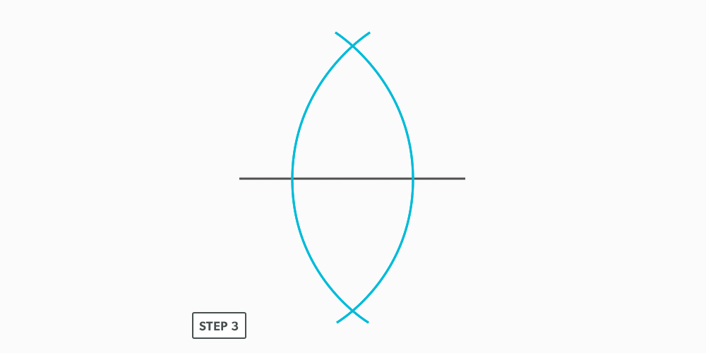
- Bisect – to divide in half
- Horizontal – a line/plane level with the horizon. Flat, level
- Obtuse Angle/Triangle – an angle/triangle with an angle larger than 90°
- Parallel – a line/plane that is equal distance from another
- Parts of a Circle
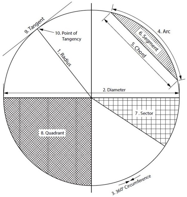
- Radius – the distance from centre to any point of the circumference or half the diameter
- Diameter – the distance across a circle at centre, twice the radius
- Circumference – the distance around a circle, perimeter of a circle
- Arc – a portion of a circumference
- Chord – a straight line from 2 points on a circumference
- Segment – the area of a circle bound by an arc and a chord
- Sector – the area of a circle bound by 2 radii and an arc
- Quadrant – a sector which equals one quarter of the area of a circle
- Tangent – a line which touches only 1 point of a circumference
- Point of Tangency – 90° to the centre of the circle
- Perpendicular – a line/plane which is 90° to another
- Right Angle/Triangle – an angle/triangle which has a 90° angle
- Vertical – a line/plane straight up and down, vertically level (plumb)
- Vertex – the point at which an angle is formed
Circle Facts:
- There are 360° in a circle.
- Circumference (or perimeter) = Pi × diameter or 2 × Pi × radius.
- Area = Pi × radius2.
Points, Lines, Angles and Shapes
In geometry we deal with many different shapes. All shapes are made up of various points, lines and angles.
Lines
We can define a point (A) as a single location on a shape or line.
A line (A-B) is made up of 2 points. There are different types of lines:
- horizontal (level with the horizon),
- vertical (up and down, also known as plumb),
- tilted (neither vertical nor horizontal), and
- arcs (a line from a radius point).
We also have lines which are parallel or equal distance apart and lines which are perpendicular or at right angles to one another.
Angles
An angle is formed at a point at where 2 lines meet (vertex). We deal with three different types of angles:
- Right angles are at 90° and are very important in layout,
- Obtuse angles, which are greater than 90°, and
- acute angles, which are smaller than 90°.
Shapes
With a combination of points, lines, and angles, we start to create shapes. Triangles (A-B-C), squares or rectangles (A-B-C-D), and circles are some of the most common shapes seen in the sheet metal industry. It is a combination of points, lines, and angles that make up different shapes —or in our case, our patterns.
9
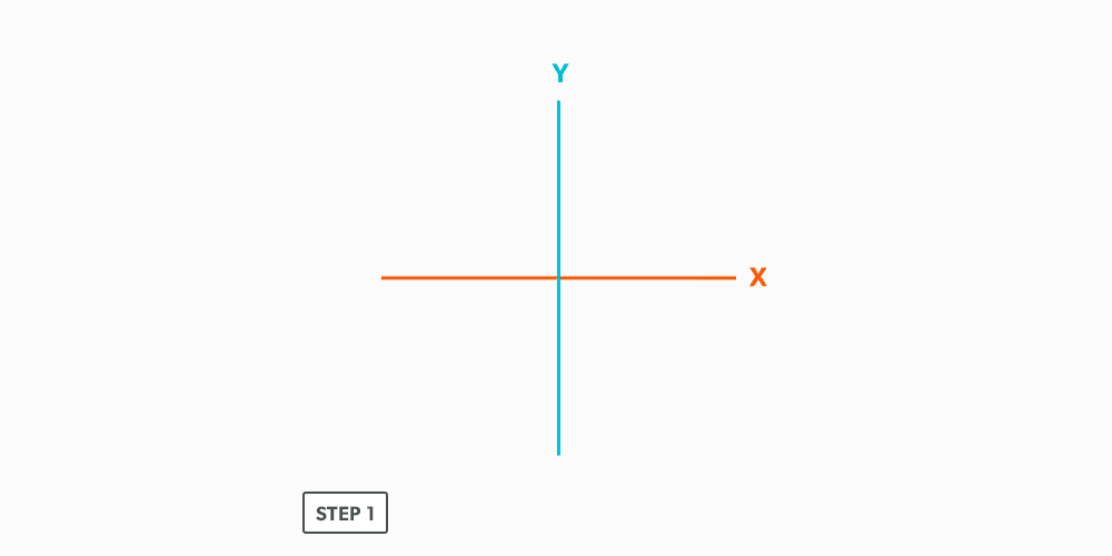
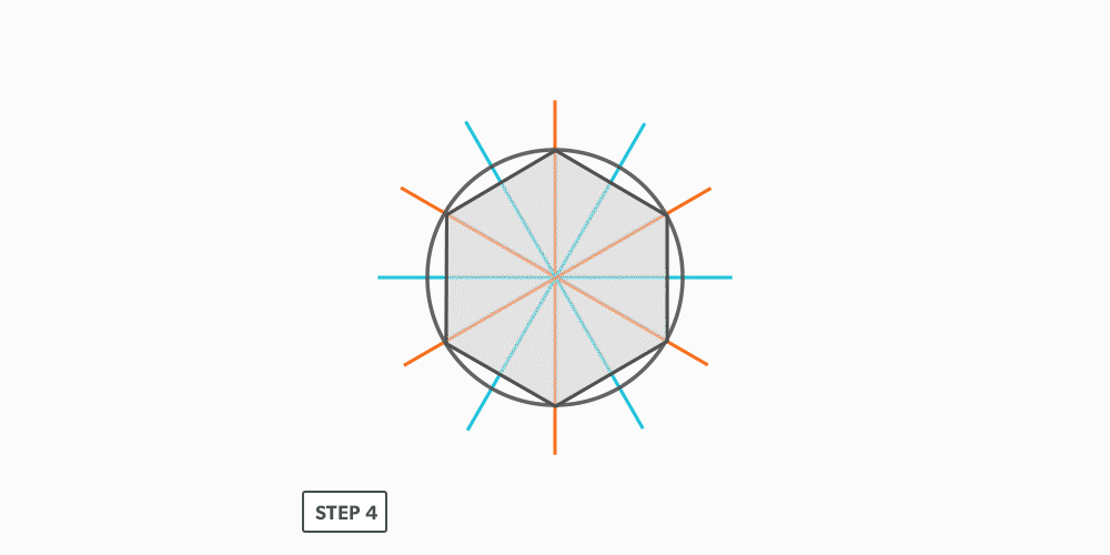
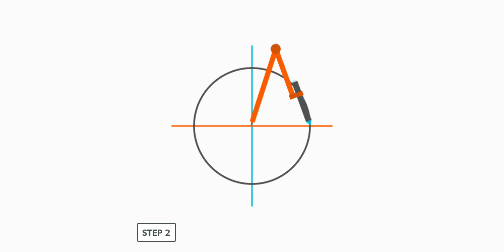
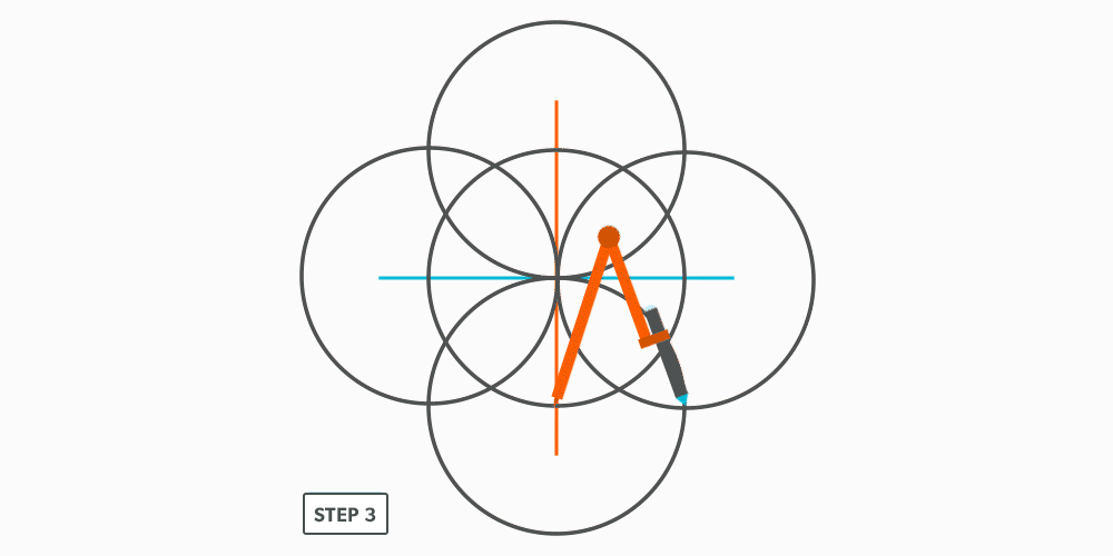
Divide a Circle Into 12 Equal Parts
10
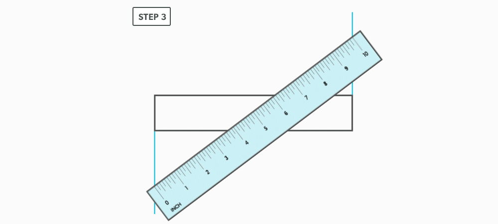
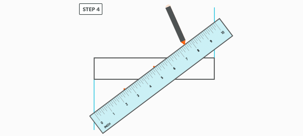
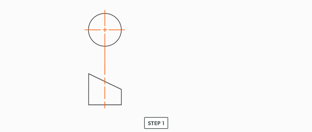
Divide a Line Using a Ruler on an Angle
12
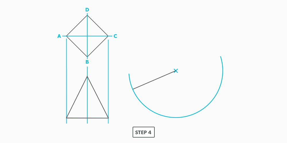
Create Other Polygons
- Choose how many side you want.
- Choose a side length. Think of this line as a radius.
- Draw a baseline double that length.
- Set you compass to the side length (radius).
- Draw a half circle from the centre of the line.
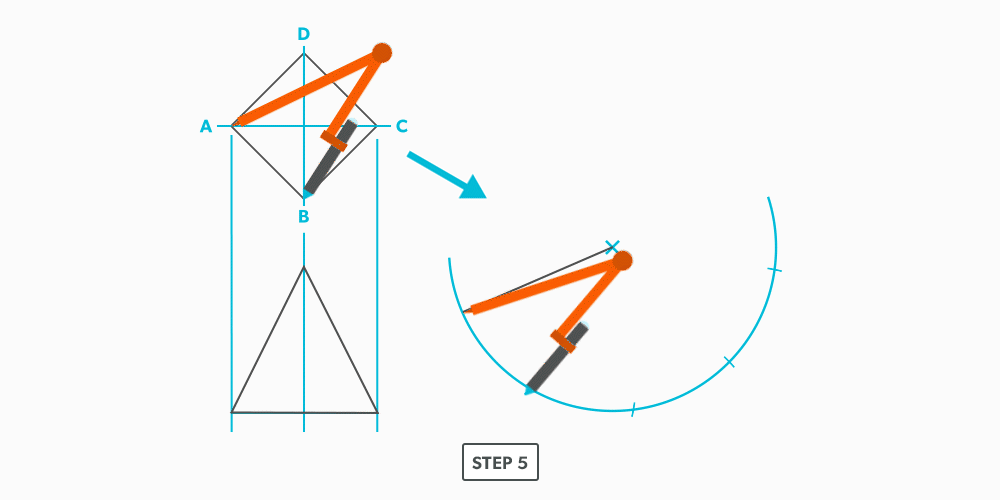
- Divide the half circle into the number of sides required and number it (other geometric construction techniques will be used here).
- Draw a line from the radius point to the third point and label the angle/triangle A-B-C. This will create an angle equal to the polygon angle (for example, five sides equals 5 ÷ 360 = 72°).
- Use “Draw an Arc Through Three Points” to find the radius point for A-B-C.
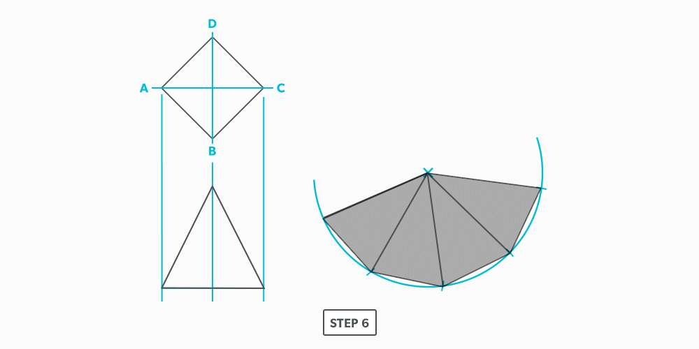
- Use this radius to draw a complete circle.
- Set your compass to the required side length and swing it along the circumference however many times needed to complete the polygon.
13
Video: Geometric Construction
II
Parallel Line Pattern Development
Introduction
When wanting to build a project, we need to first imagine it. The process of pattern development gives us the ability to take that visual representation and actually create the object. It allows us to turn two-dimensional metal into three-dimensional objects, which is the basis for everything we fabricate.
Consider a globe and a map. The map is a 2D representation of a 3D object. What should the map look like? Is it truly flat? Well, maybe some would argue, but a map is not a true representation of the Earth until we remove some of it. The actual shape of the map will have numerous “cut outs” which would allow it to form a sphere. This is a form of pattern development.
- Understand the parallel line pattern development processes.
- Understand the “language” of layout.
- Allowance – the material needed for a specific component. “We must allow this much extra.” Usually a seam for connection.
- Auxiliary Line – an extra element line added, different from the standard divisions.
- Elbow Rule – the number of pieces of a round elbow times 2 then minus 2 (# of pcs × 2 − 2) gives us the number of gores in the elbow.
- Element Line – a line representing an edge or bend.
- Elevation View – looking at the front or side of something, to have elevation (height), 2D.
- Gore – a part of a round elbow which allows us to calculate the miter angle.
- Miter – an intersection of 2 pieces, an irregular cut on the end of something.
- Pattern – the shape of the object, still in 2D form.
- Plan view – looking down at something, a “birds eye view,” “floor plan,” (2D).
- Profile – a half of a plan view, drawn on the outside of an object.
- Sector – a special profile which is inside of an object, a section view.
- Stretch-out -a shape which has been “stretched out,” to take a perimeter and make it straight.
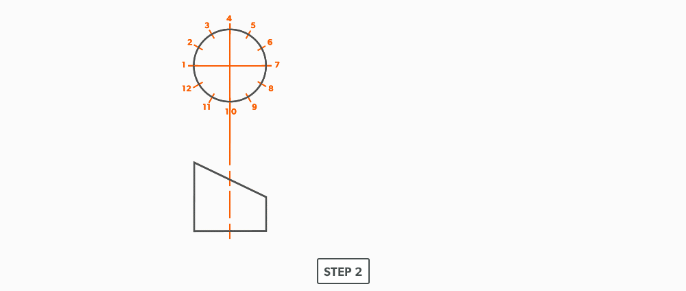
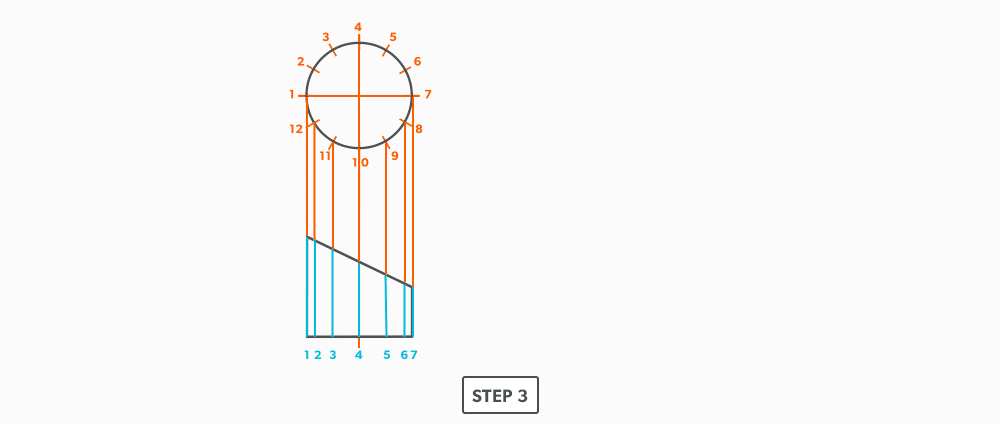
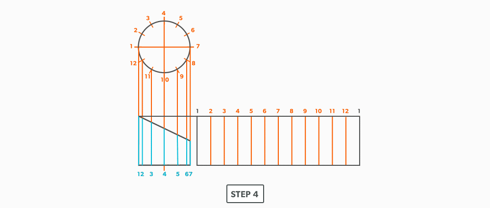
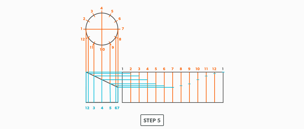
Parallel Line Development
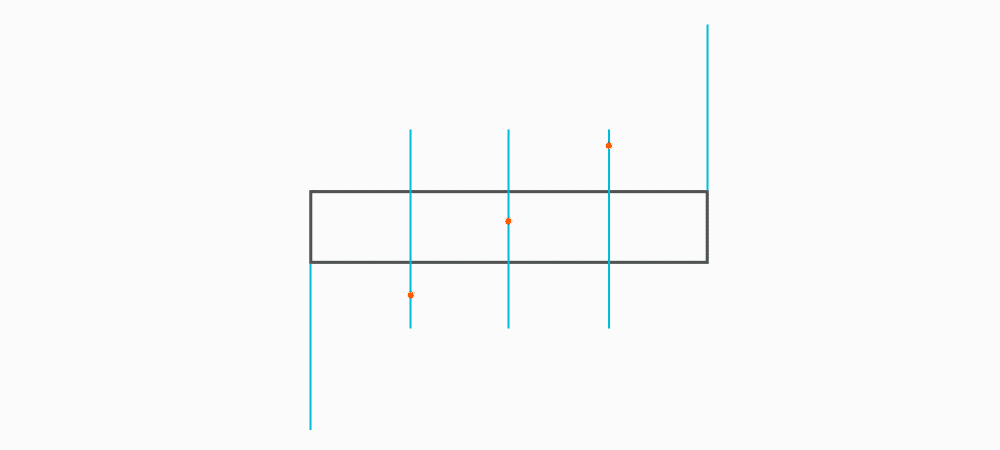
The process of pattern development is the way we turn 2D sheets of metal into 3D objects. A parallel line is one of the basic forms of layout. We use it when element lines (bends) on an object are indeed parallel. The two ends of the part must be the same. Consider a gutter: It may have curves and bends and angles, but each end is the same shape. The element lines and bends are all parallel. This is the only factor which will allow parallel line pattern development to be used.
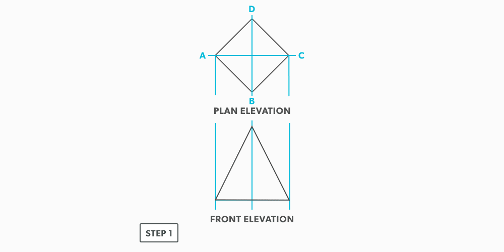
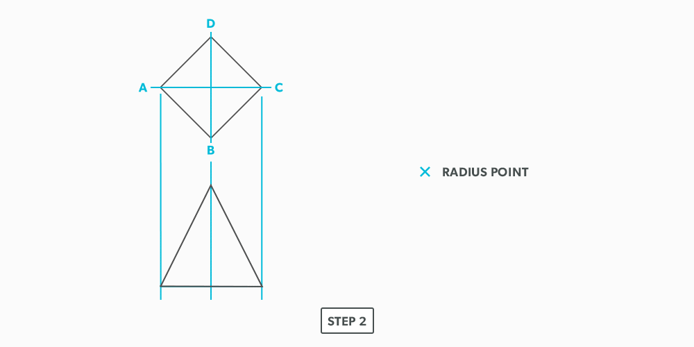
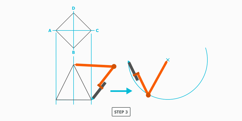
Basic Steps
- Draw a full plan and elevation view, complete with all element lines and miter lines.
- Draw a stretch-out, complete with all element including auxiliary lines.
- Transfer the lengths (height) of the element lines from the elevation view to the corresponding element line on the stretch-out.
- Join the point to create the pattern.
15
Equal Diameter 90 Degree Tee
16
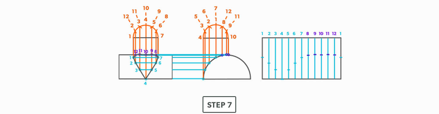
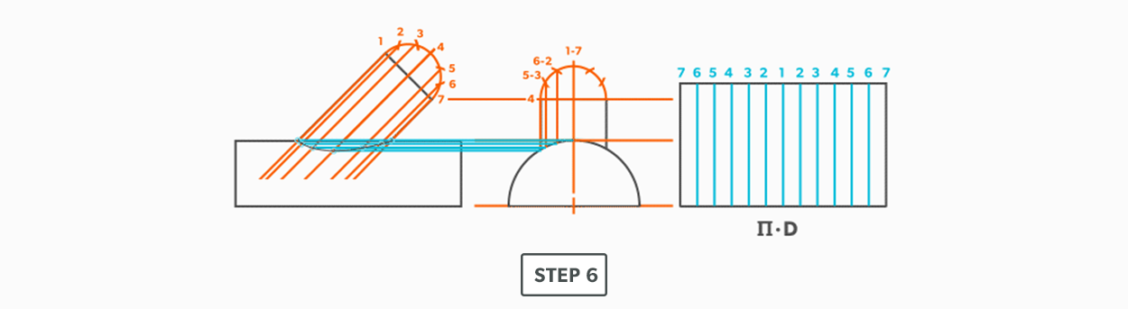
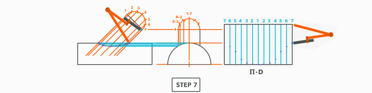
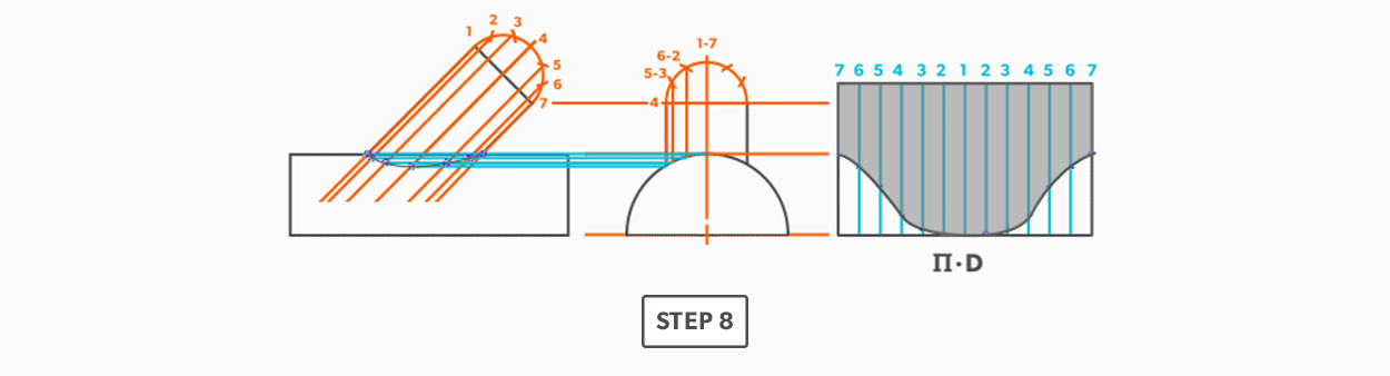
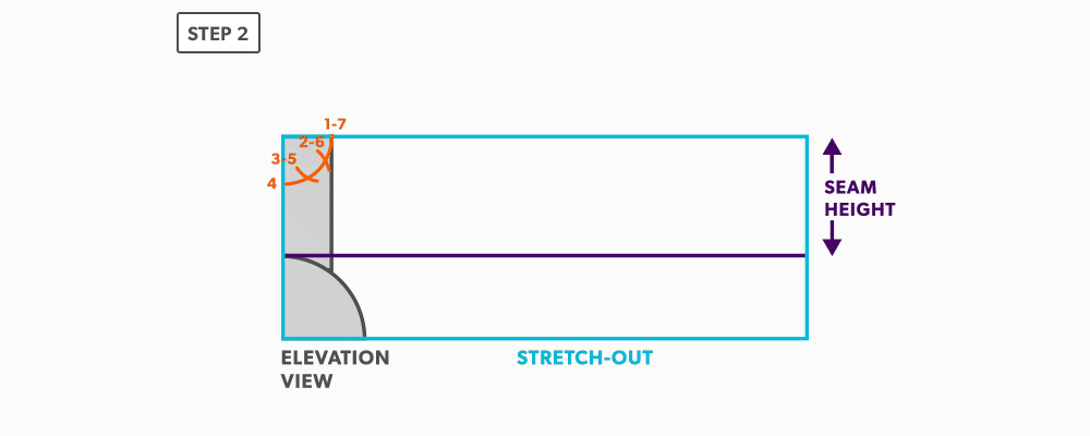
Unequal Diameter 90 Degree Tee-Shop Method
We will continue to use short-cuts. In this example, we move the views into the blank size and minimize our drawing. It still gives us the point “where the tee hits the pipe” and it is much more manageable to do in the shop. This method can be used on any tee besides an oblique tee.
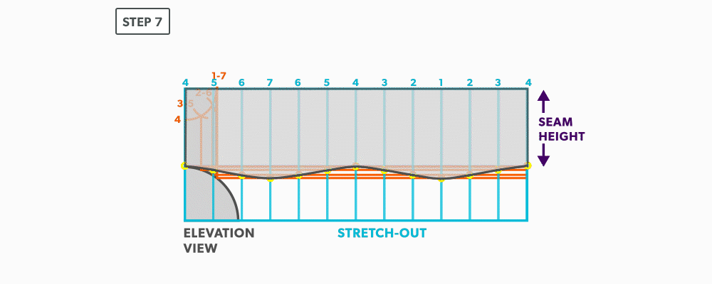
- Calculate the blank size. Use the stretch-out for one dimension (horizontal) and the seam height plus the radius of the pipe for the second (vertical) dimension. Add any seam allowances on before shearing the blank size.
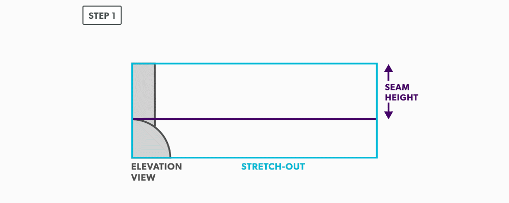
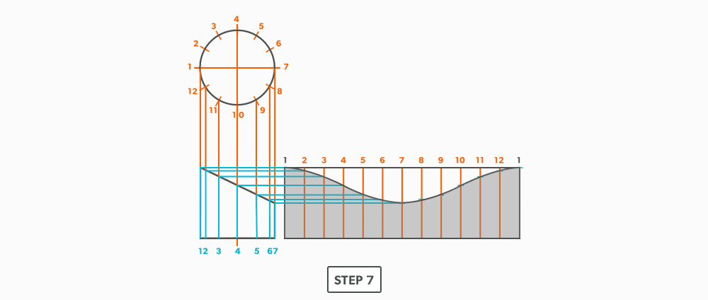
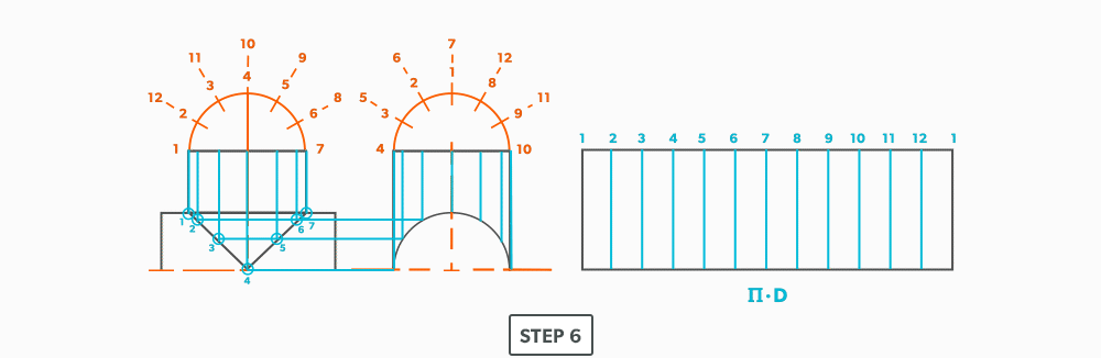
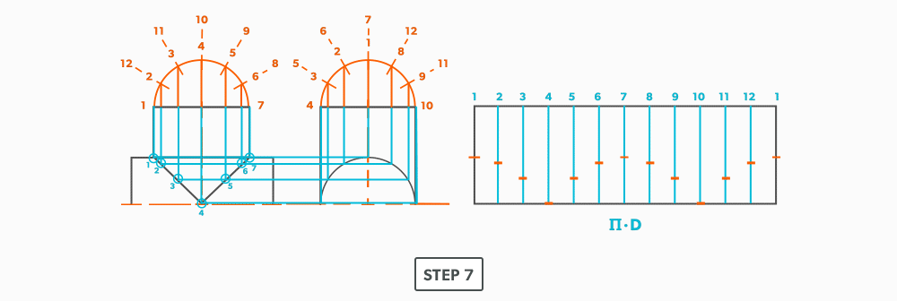
- With your dividers, swing the radius of the pipe to 180° at the bottom of the blank. Then, from the same radius point, swing the radius of the tee and divide it into 6 equal parts (see Divide a Circle Into 12 Equal Parts) and label it. Remember that only the tee is divided. Also, notice that the half circles are symmetrical, so a quarter circle is the minimum required in this case.
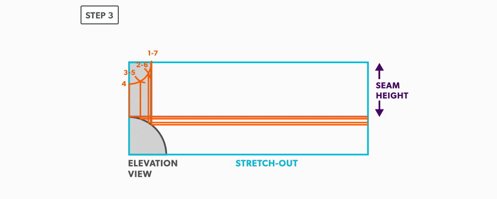
- Project the divisions of the tee vertically into the pipe and where they intersect, project them horizontally.
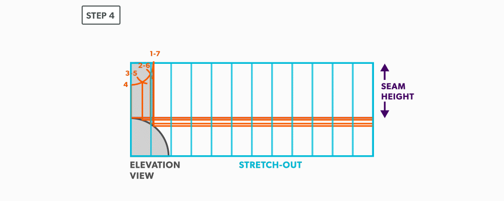
- Divide the blank size into 12 equal parts (see Divide a Line Using a Ruler on an Angle). Remember to only divide the circumference, any seam allowance should not be included in the divisions.
- Label the stretch-out to match the profiles, starting at the seam.
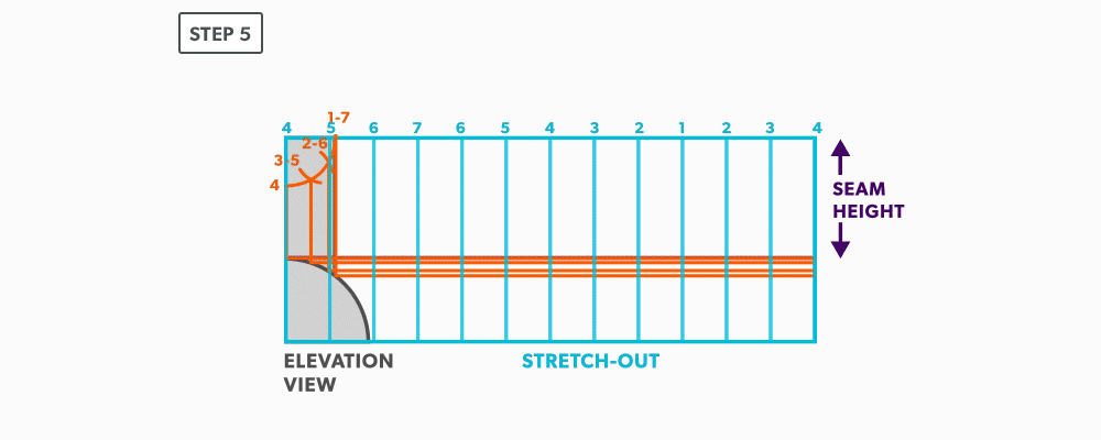
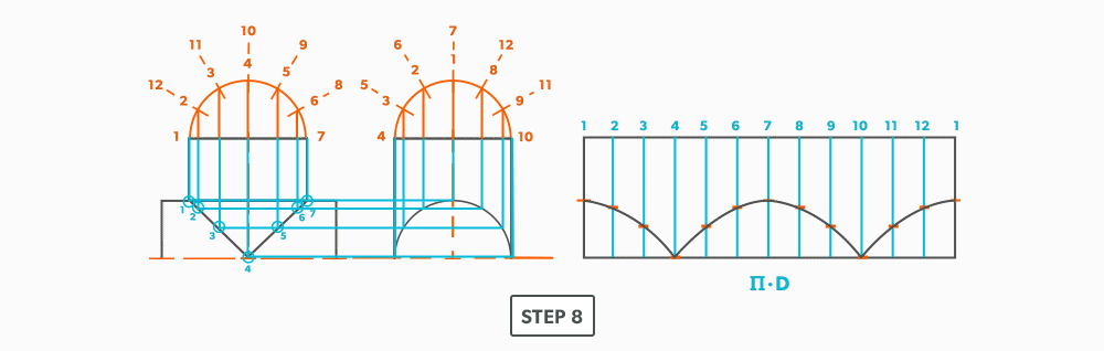
- Start the pattern at your seam and follow the labeling. Notice the pattern of over 1, up/down 1, until you reach the last line and then it reverses.
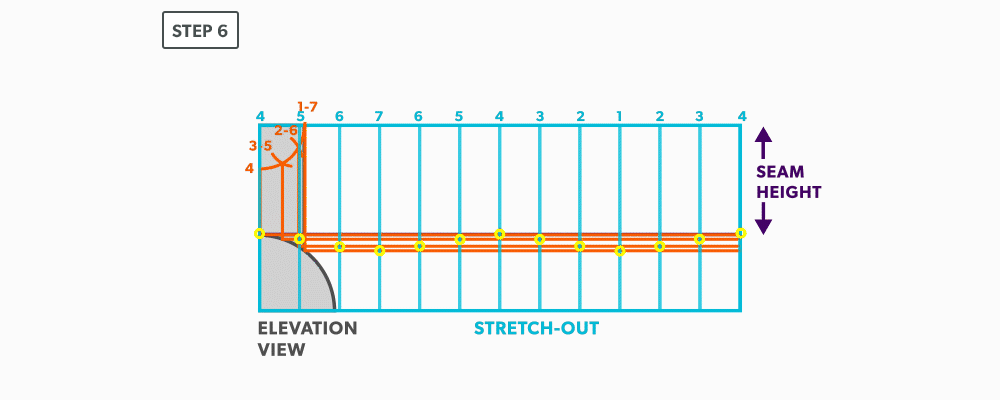
- Draw the miter line on the pattern with a flexible curve
19
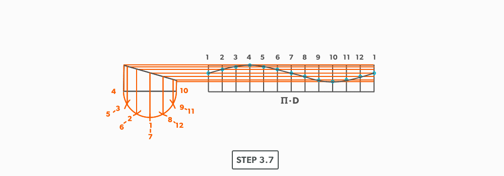
Round Elbow
For this example we will use a 6″ diameter-6″ throat radius-4pc-90°.
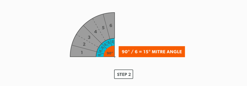
- Use the elbow rule (# of pcs × 2 − 2) to find the number of gores. For our example, it is 4 × 2 − 2 = 6. Each end piece is made up of one gore and each middle piece is made up of two gores.

- Use the angle of the elbow divided by the number of gores to find the miter angle. In our case, 90° ÷ 6 = 15°.
- Now that we know the miter angle is 15°, we can use an end gore and lay it out similar to a “Pipe on a Miter” (see Pipe on a Miter).

- Draw an elevation view, complete with the miter line.

- Draw a profile below (see Divide a Circle Into 12 Equal Parts) and label it.
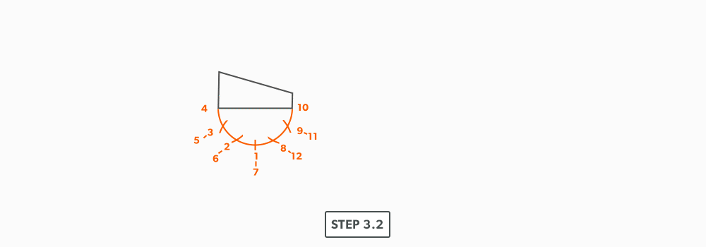
- Project the profile divisions up into the elevation view.
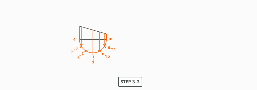
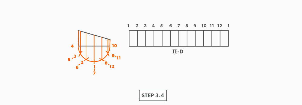
- Draw the stretch-out (6 × Pi) directly to the right of the elevation view and divide it into 12 equal parts (see Divide a Line Using a Ruler on an Angle). Label it to match the elevation view and make sure to start the labeling on centre of the gore. Add any required seam allowances outside of the stretch-out.
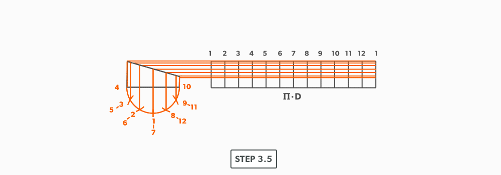
- At the points where the element lines cross the miter line, project them into the stretch-out.
- Following the labeling, circle the intersection points on the stretch-out. Don’t put a dot over the points, but circle around them.
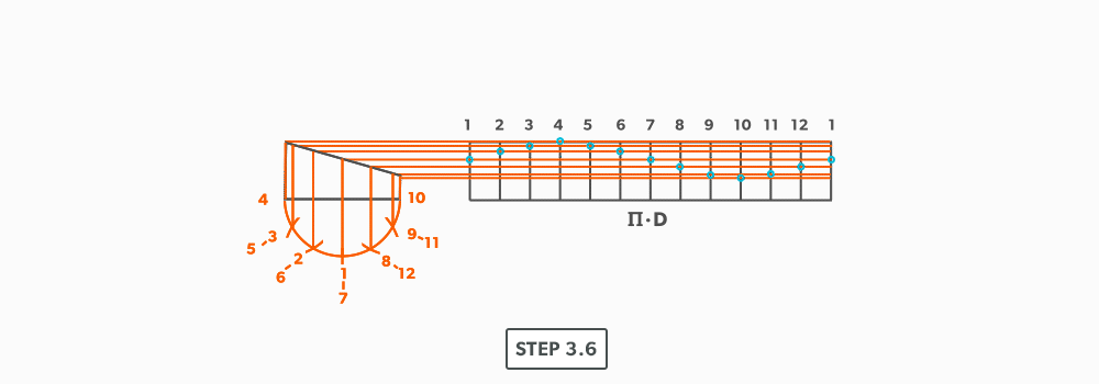
- Using a flexible curve, join the points to draw in the miter line, completing the pattern.
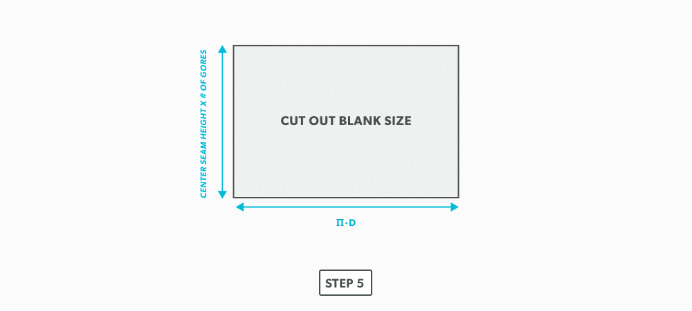
- We now need to finish the calculation for the blank size of the elbow. We already have the stretch-out, but we need the height. This is found by multiplying the seam height by the number of gores. For our example, simply measure the elevation view and find the height of the element line on centre of the gore. This should be 2 7/16″. 2 7/16″ × 6 =14 5/8″.
- Now, cut out the blank size.
- Mark the seam height of each gore vertically on the stretch-out.
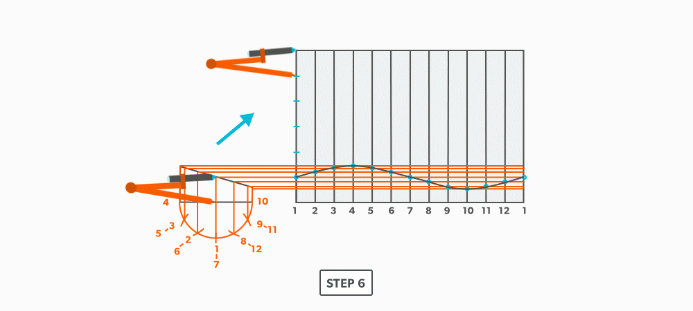
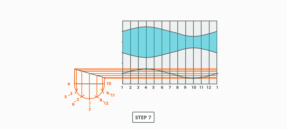
- To complete the elbow, trace or transfer the first gore pattern onto the blank and cut it out. Then, flip it and trace it for the rest of the gores. Do not flip left to right, only up and down and remember that you must leave 2 seam heights (2 gores) for the middle pieces. This will allow the seams to be orientated on opposing sides and produce the “fish” pattern.
III
Radial Line Pattern Development
In Parallel Line Pattern Development, we required parallel element line or bends. Some objects are of a conical shape and parallel line will not work on them. Rather, we will look at using Radial Line Pattern Development.
In radial line, we develop patterns for shapes that have a taper, all element lines (bends) must radiate back to a common point, a radius point. We need two things for this process to work:
- A radius point that is on centre (right cone).
- A radius point that is within a reasonable distance.
So, when we find ourselves determining if radial line will work, we look at those two things. If the cone is a scalene or oblique cone, it will not work. If a radius point is 40 feet away, it is not worth the effort with this process, another should be chosen, but if it will fit in our bench space, then it will work.
Being one of the simplest forms of layout, it allows us to create these patterns with accuracy and speed. If we can use radial line, it is an effective and efficient choice.
- Understand the process of Radial Line Pattern Development and its uses.
- Understand the language of Radial Line.
- Apex – the intersection point of a cone, as seen in the elevation view.
- Slant Height (small or large) – the hypotenuse of a cone, outside edge. The slant height is always a true length in the elevation view.
- Stretch-Out Angle/Arc – the angle or arc which encompasses a radial line pattern.
- Frustum – a cone with the top cut parallel to the base.
- True length – a dimension or line that is not distorted by the view.
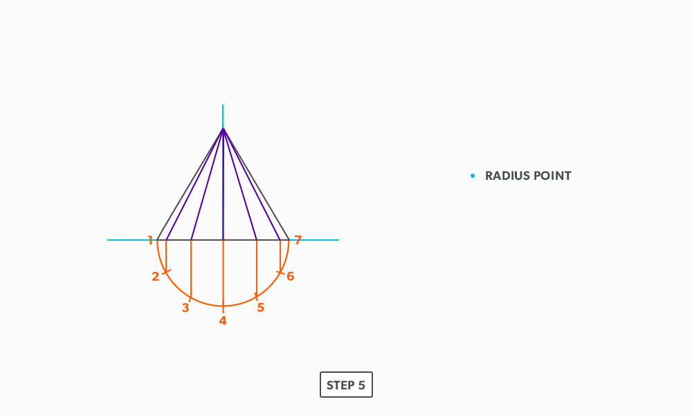
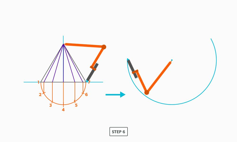
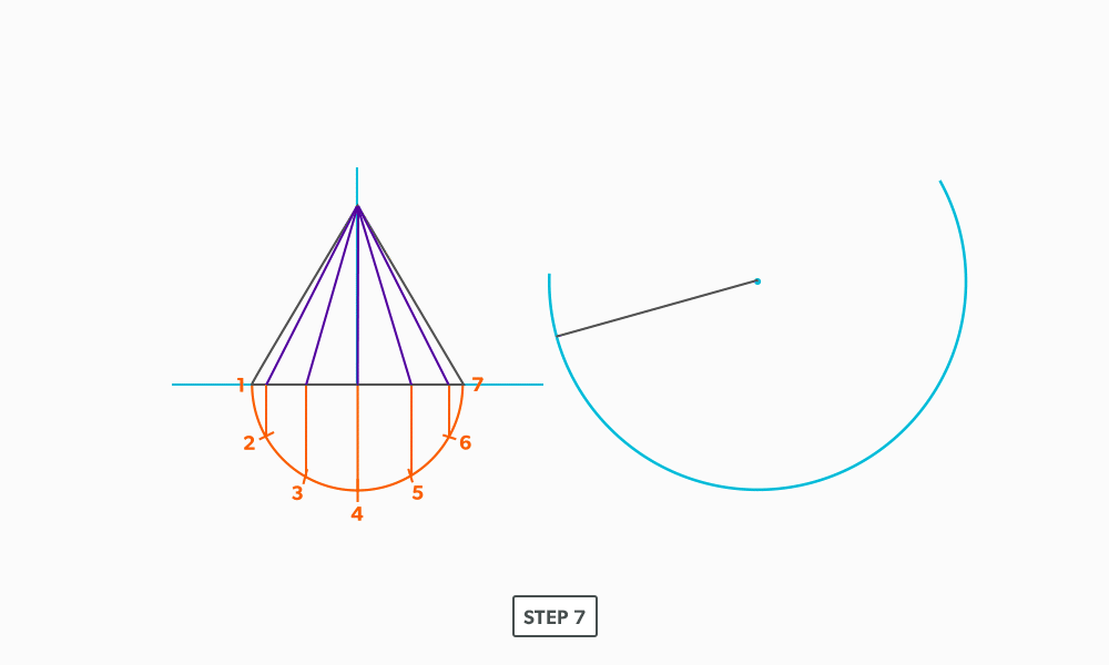
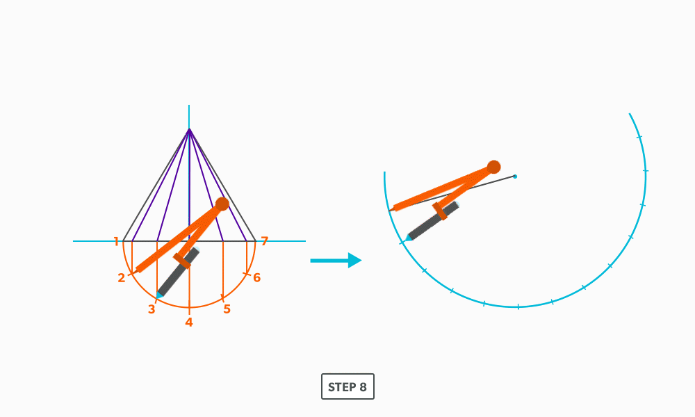
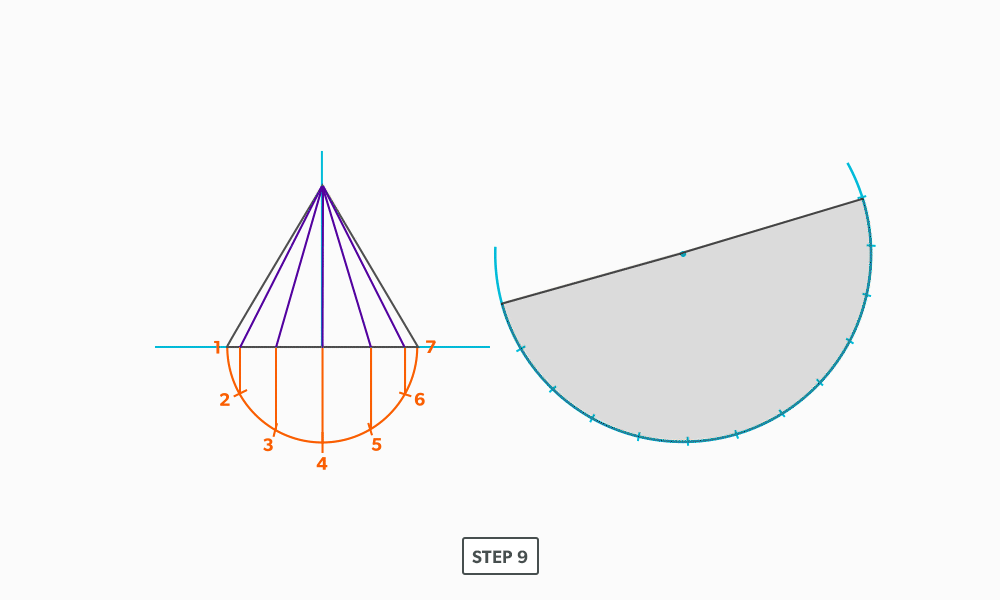
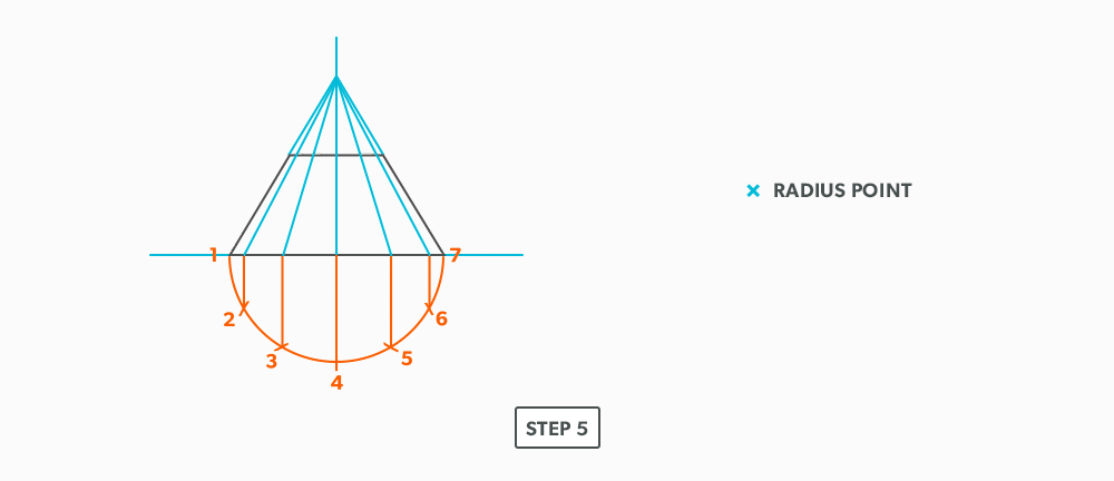
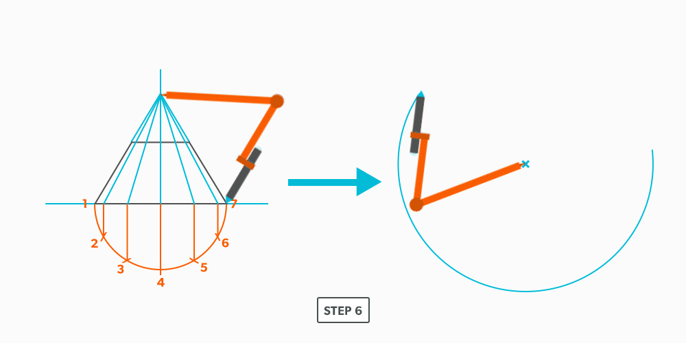
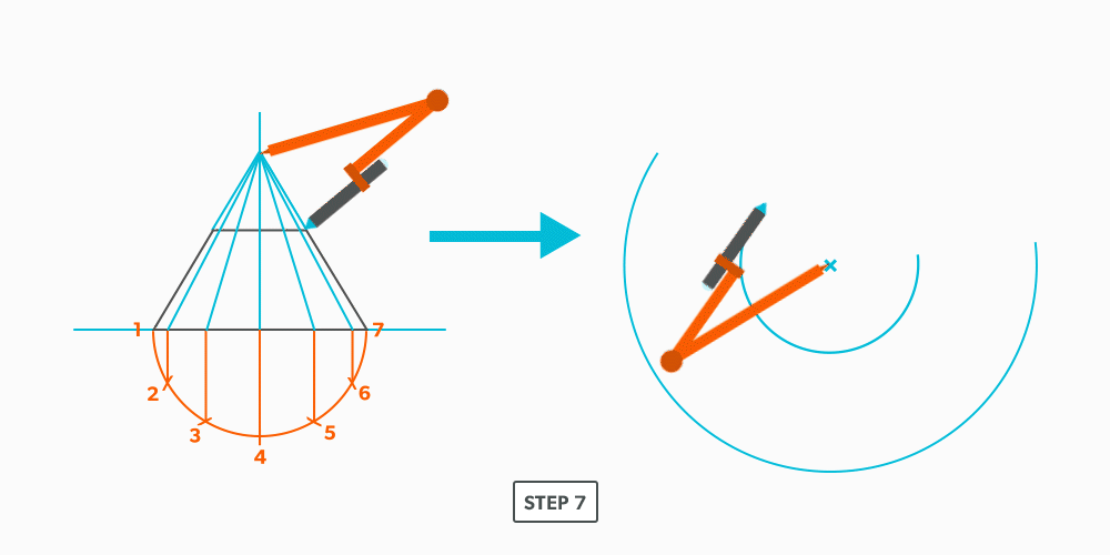
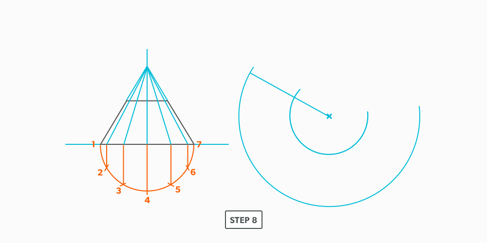
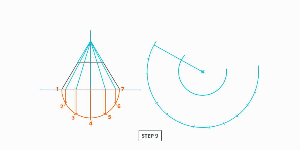
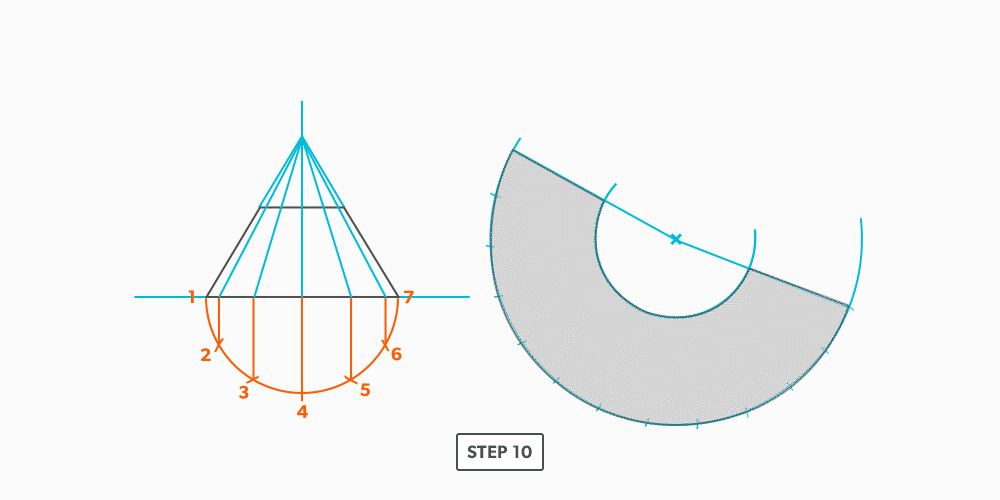
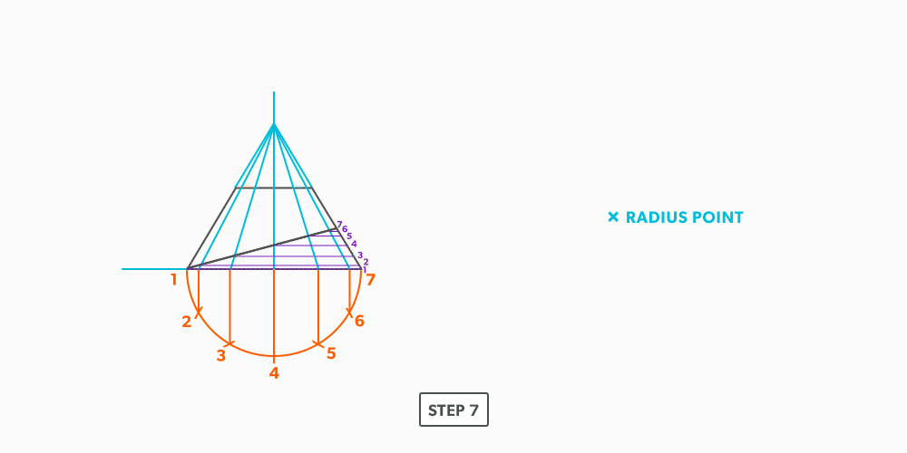
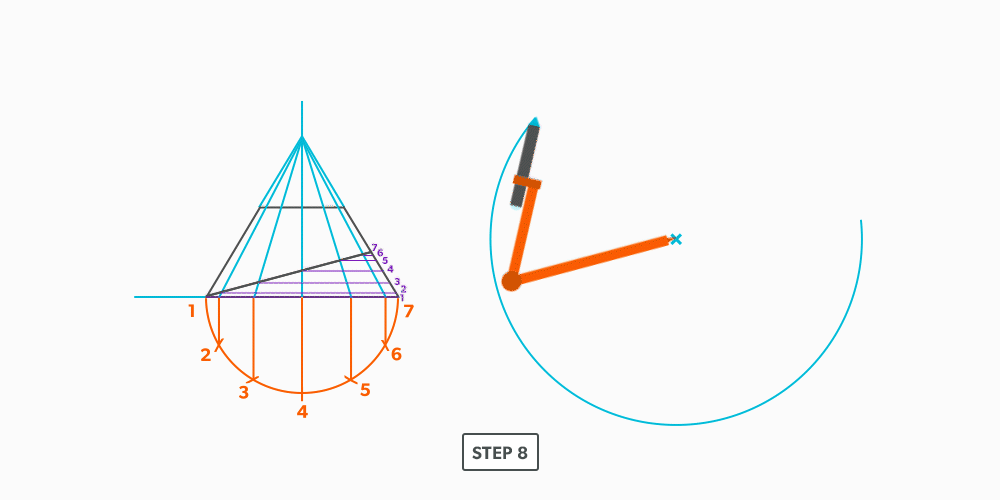
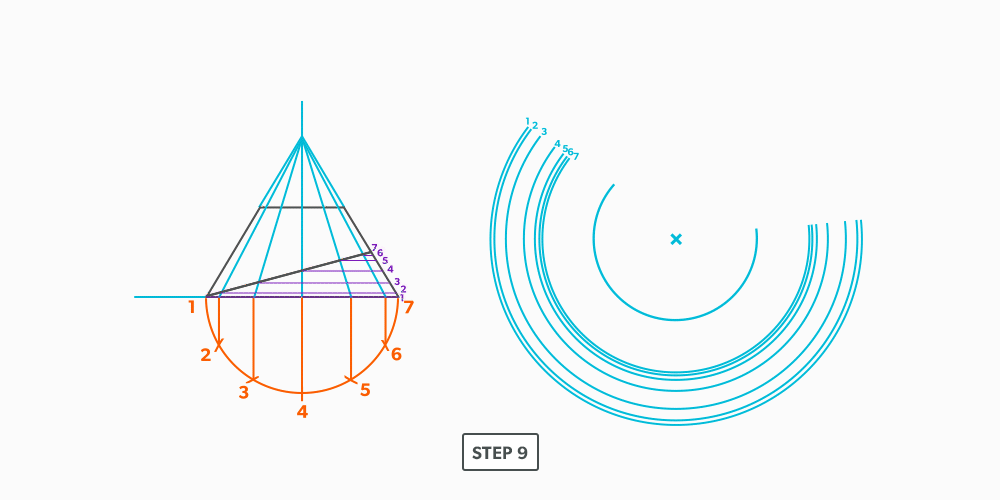
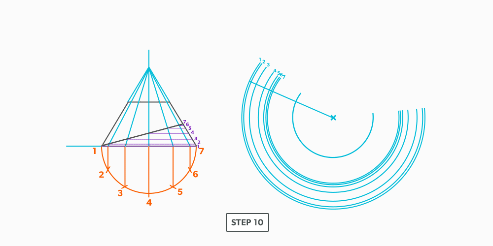
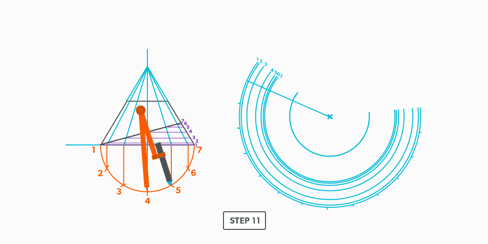
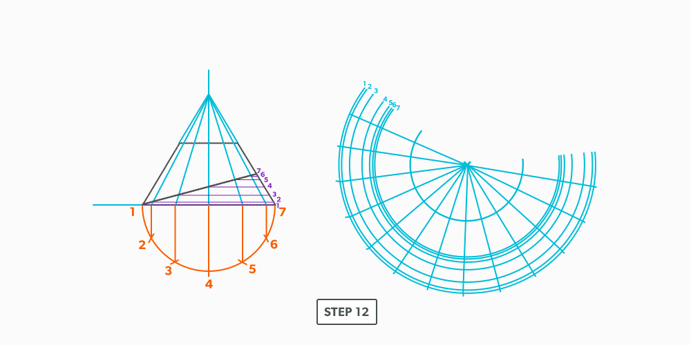
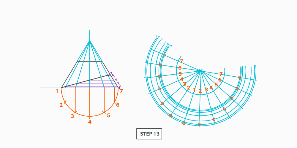
Basic Steps
- Draw a full elevation view and plan view complete with all element lines.
- Swing the slant height with your compass. Remember, in the elevation view, the slant height is always a true length. This arc is also called the stretch-out arc.
- Make the length of the stretch-out arc equal to the distance/circumference of the base. There are many ways to accomplish this, but we will focus on the most common method, using step-offs.
A step-off can come from calculating the circumference and dividing by 12 or simply set your compass to one of the profile divisions. Keep in mind that either way will have accuracy problems, it depends on how accurate the pattern must be. We will cover the most accurate method, layout by mathematics, in another unit later.
IV
Triangulation
When we looked at both parallel line and radial line pattern development, we saw fairly simple and limited layout process. We have conditions that must be met in order to use them. Triangulation is the process used when nothing else works. There are very few conditions in which triangulation will not work. It is the most complex and time consuming, but it allows us to create patterns of endless possibilities. When all else fails, triangulation will work.
- Understand the process of Triangulation Pattern Development and its uses.
- Learn Triangulation terms.
- True Length – a dimension or line that is not distorted by the view.
- True Length Diagram (TLD) – a 90° corner in that we use to find the actual length of a line.
- Triangulation from Plan View – the length of an element line, set 90° to the vertical height, gives the true length of that line.
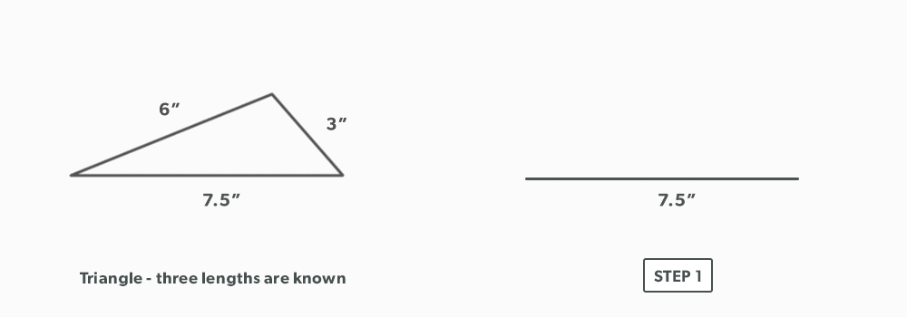
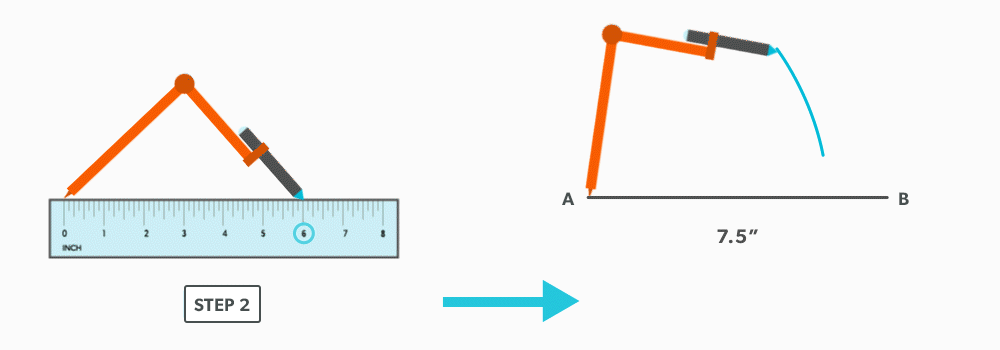
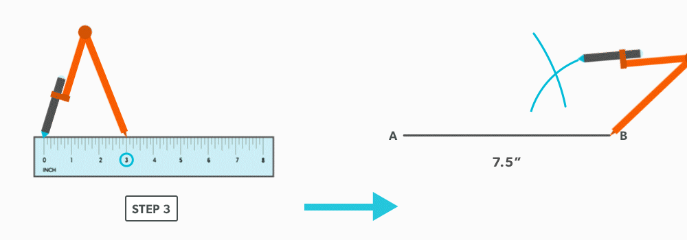
Triangulation is defined as using two known points to create a third. If we think back to geometric construction, we created triangles such as a 3-4-5 in this manner. The development of patterns using triangulation is an extension of that process. Developing one triangle after another, we build 2D patterns for 3D objects.
In this unit, we will focus on Triangulation from plan view.
Let’s look at a right triangle in orthographic terms. If we look down on a triangle (plan view), we only see the one leg of the triangle. If we look from the front (elevation view), we see the other leg. When we look from the right side, we see a full view of the triangle, with all three legs. The right side is the only view that gives enough information to see the whole triangle.
The same is true when we think of these ideas in relation to a 3D object. With few exceptions, we don’t actually see true lengths of the element lines for an object in the plan or elevation views. They are representations. Think again of the triangle in orthographic projection. If only the hypotenuse was drawn, not a full triangle, the plan and elevation views would still look the same as it did when we looked at the triangle. This is true of any 3D object. The plan and elevation views only show a representation of the hypotenuse from different views. Remember that the element lines or edges only represent the outside of the object.
So, to triangulate a pattern for an object, we must find the outside lengths of all the element lines, the hypotenuses. We must get all element lines from an object into a right side view. With a 3D object, this takes rotating the object over and over, putting each line individually into a right side view. This would take a tremendous amount of work, but, we can do this quite easily by using what is called a true length diagram. This is know as finding true lengths and is the foundation that all triangulation is built upon.
For triangulation, we must find the true lengths of the element line before we create any triangles. And the true lengths are the hypotenuses between the plan length and vertical height. This is the way we triangulate from plan view.
If we again think of the plan view, we have the length of one leg. It doesn’t matter how the line is orientated, it is shows us how much the outside edge (hypotenuse) is leaning. We also have the vertical height of the triangle in the front view. So, if we take these two known lengths and place them in a 90° corner, it shows us the same as the right side. It show us the hypotenuse. It shows us the true view of the element line. This is known as a true length diagram.
Basic Steps
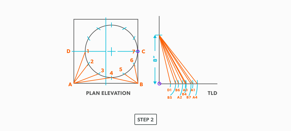
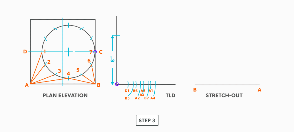
- Draw a full elevation view and plan view.
- Draw in all element lines in both views. An element line which appears as a dot in one view, is a true length in the other view. As well, a line parallel to the x-axis in the plan view is also a true length in the elevation view.
- Label the element lines. It is common to label round shapes with numbers and square/rectangular with letters.
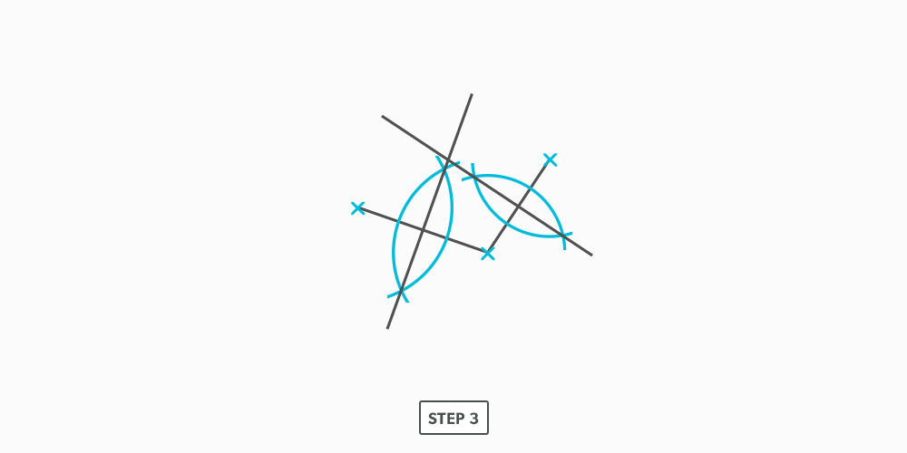
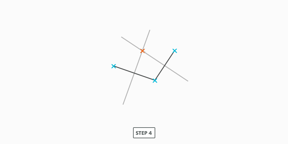
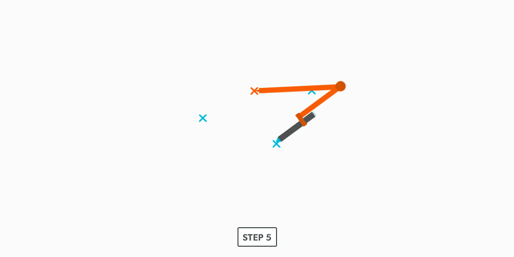
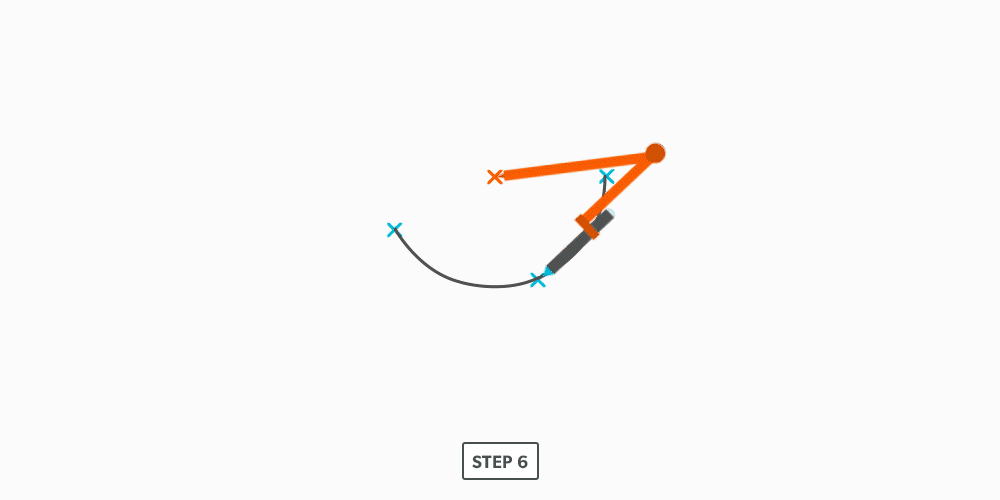
- Create a 90° corner for a true length diagram and transfer all the element lines from the plan view into it.
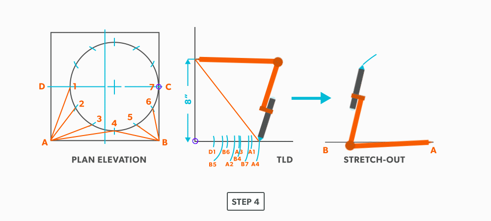
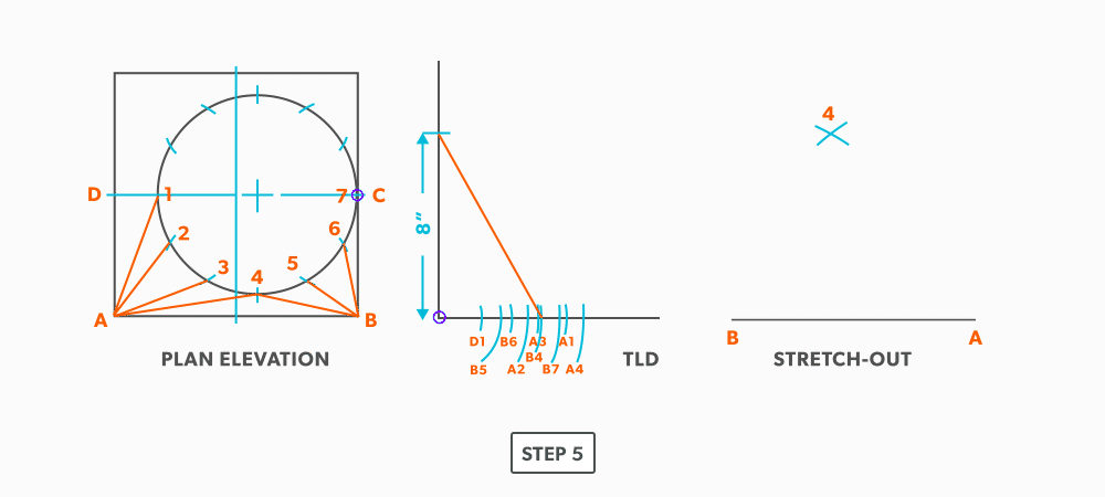
- Start the pattern with a line of two known points. There will always be two known points to start from, either a horizontal or vertical line.
- Using triangulation (see Construct Triangles – “Triangulation”), create the third point.
- Repeat until all the element lines have been used.
- Draw in all the element lines and outside edges to complete the pattern.
24
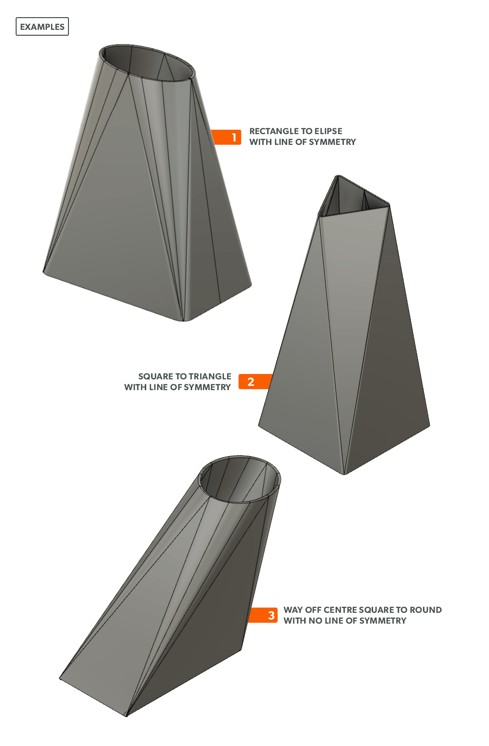
On-Centre Square to Round
A square to round can only be formed in halves, so we always develop a half pattern.
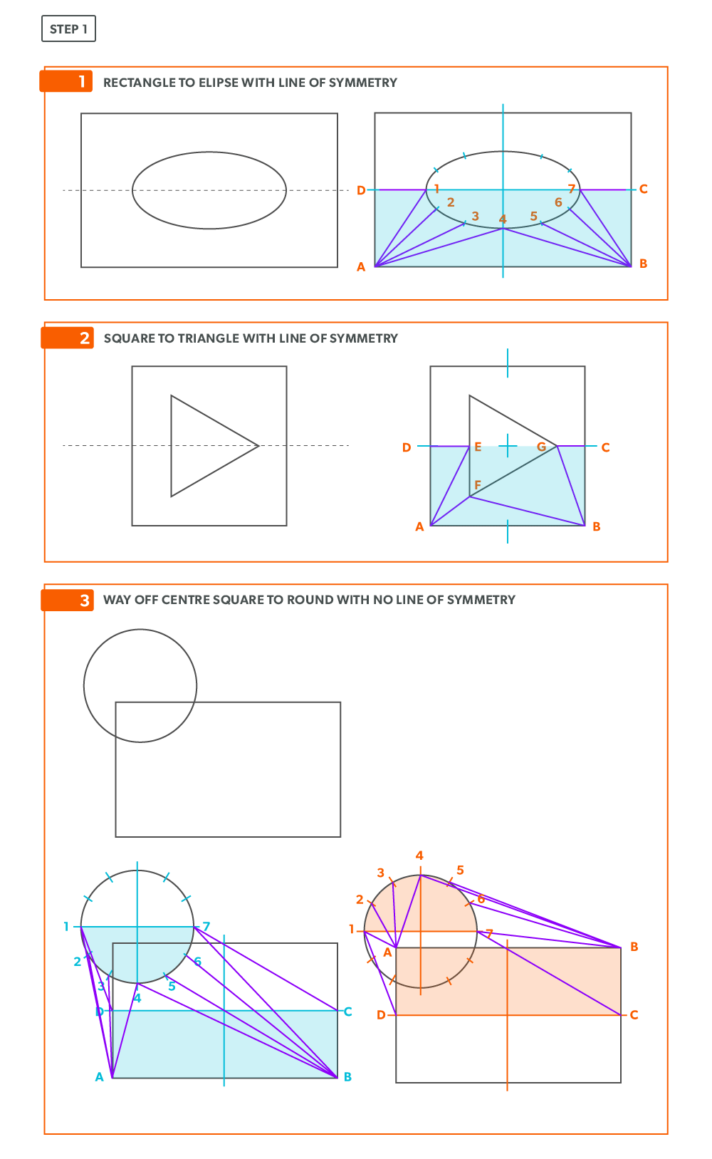
- Draw a full plan view complete with all element lines and labeling. Label one half of the plan view, the round end with numbers and the square end with letters. Notice the lines of symmetry in the plan view. Parts of the drawing can be deleted because of this symmetry. In this case, it is on centre in both directions, so a quarter plan view is the minimum required to avoid duplication. But, sometimes it is easier to draw at least a half plan, there is no harm in drawing more than the minimum required.

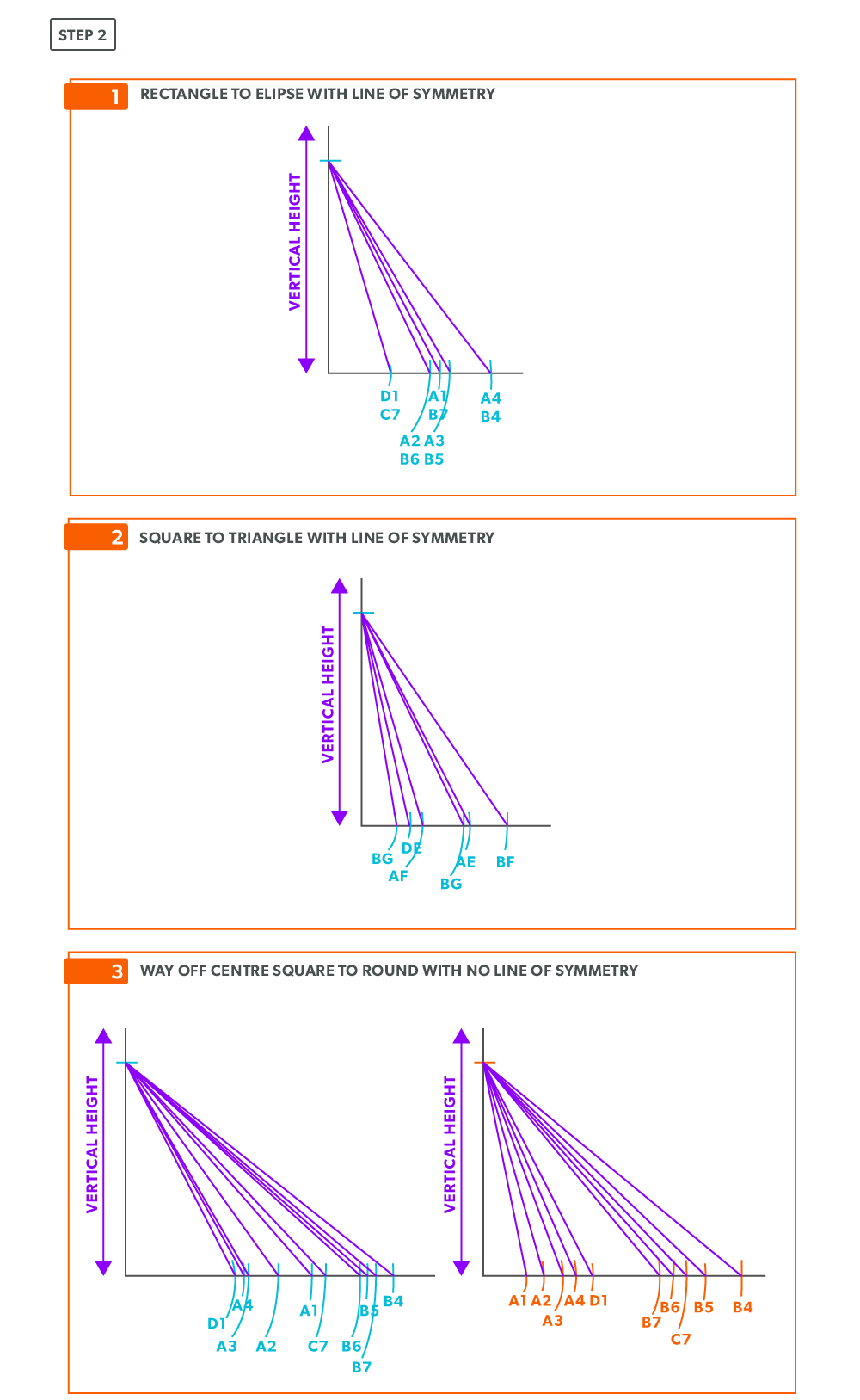
- Create a true length diagram (TLD) with the vertical height of the fitting and a horizontal length long enough to fit any of the element lines.
- Take the element lines A-1, A-2 and C-7 from the plan view and place them in the horizontal of the TLD. In this case, all other lines will be a duplicates of these 3 lines. Still, label the TLD with ALL of the element lines so you don’t make a mistake!!!
- Draw a baseline equal to line A-B. We are now ready to triangulate
- From the TLD, pick up the true length of line A-4 and swing it upwards from point A towards the centre. Then swing it from point B. Where these arcs cross is point 4. We now have our first triangle, A-B-4. This is our first step of triangulating. Remember that triangulation means using two known points to create a third. In this case, the known points are A and B and the unknown is 4.
- Next, pick up true length of line A-3 and swing it from point A. In this step our two known points are now points A and 4 (or B and 4) and the unknown is 3. In each step, we will use the last point created as one of our new known points. Because the fitting is symmetrical, continue to work both sides at the same time. We will only discuss one side here, but the steps repeat on the other side.
- Pick up line 3-4, a step-off, from the plan view and swing it from point 4, to create point 3. When we look at our plan view, we have labeled it in a way that numbers are at one end and letters on the other. So, when we go from one end to the other (number to letter), we need to find the true length, but when we go from number to number (or letter to letter) we don’t have any elevation change involved. We are just going horizontally along the end, which means it is a true length in the plan view.
- Pick up line A-2 and swing it from point A.
- Pick up a step-off and swing it from point 3, to create point 2
- Pick up line A-1 and swing it from point A.
- Pick up a step-off and swing it from 2, to create point 1.
- Pick up line C-1 and swing it from 1. This is our first step where we are not swinging from A; we now must swing from 1. Always be thinking of the known points and the unknown. We must always swing an arc from a known point. For this triangle, the known points are A and 1 and the unknown is C. So, line C-1 has to be swung from 1 since we don’t know where C is yet.
- Pick up line A-C from the plan view (remember that letter to letter is true length) and swing it from point A, to create point C. The way to check our work is this last triangle should be a right triangle. Point C should be 90°, if it’s not, go back and check your work.
- Draw in the all the element lines and outside edges, using a flexible curve for the round end.
- Cut out and trace the pattern for the other half.
25
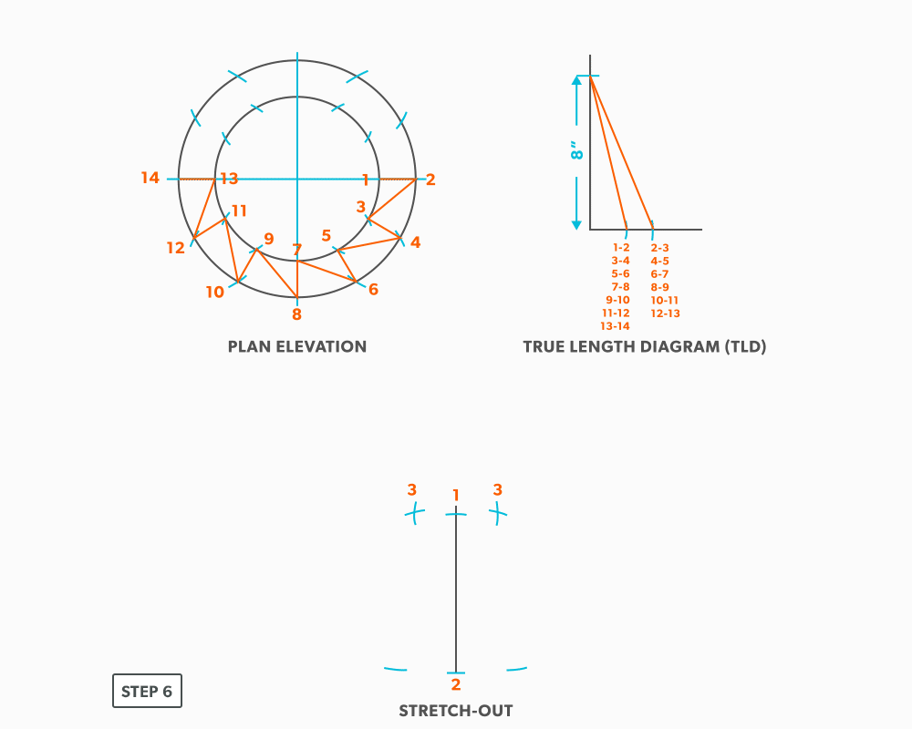
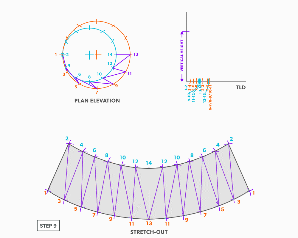
On-Centre Round to Taper
- Draw a full plan view complete with all element lines and labeling. Label one half of the plan view, travel from large end to small end, zig-zagging back and forth with the numbering 1-14. Notice the lines of symmetry in the plan view. Every round to round will be on centre one way, but it is always worth drawing the whole thing.
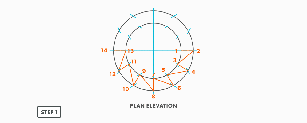
- Create a TLD and label all the element lines. Remember, any element line which travels from one end of the fitting to the other, will need to be put into a true length diagram.
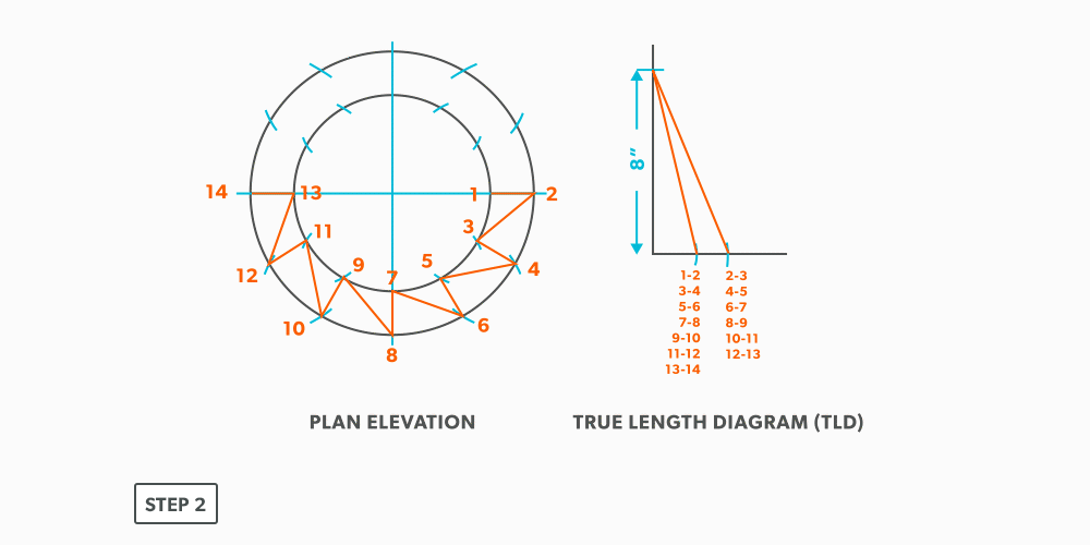
- Draw a vertical line equal to the true length of line 1-2. Square to rounds always start with a horizontal line and round tapers always start with a vertical line. We are now ready to triangulate.
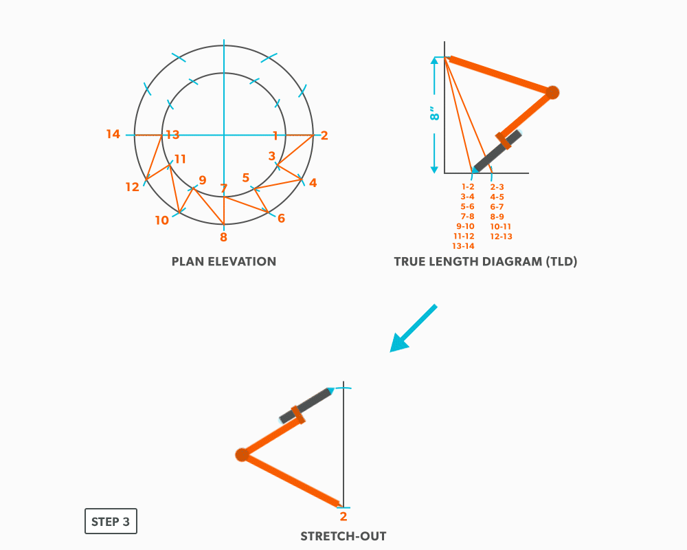
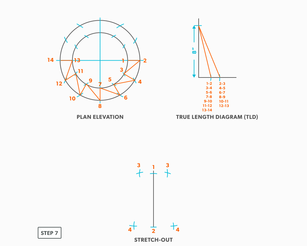
- From the TLD, pick up the true length of line 2-3 and swing it from point 2, back towards point 1. Remember to work both sides at the same time.

- Next, pick up step-off 1-3 and swing it from point 1, to complete point 3. When we look at our plan view, we have labeled it in a way that odd numbers are at one end and even on the other. So, when we go from one end to the other (odd to even), we need to find the true length, but when we go from even to even or odd to odd we don’t have any elevation change involved. We are just going horizontally along the end, which means it is a true length in the plan view.

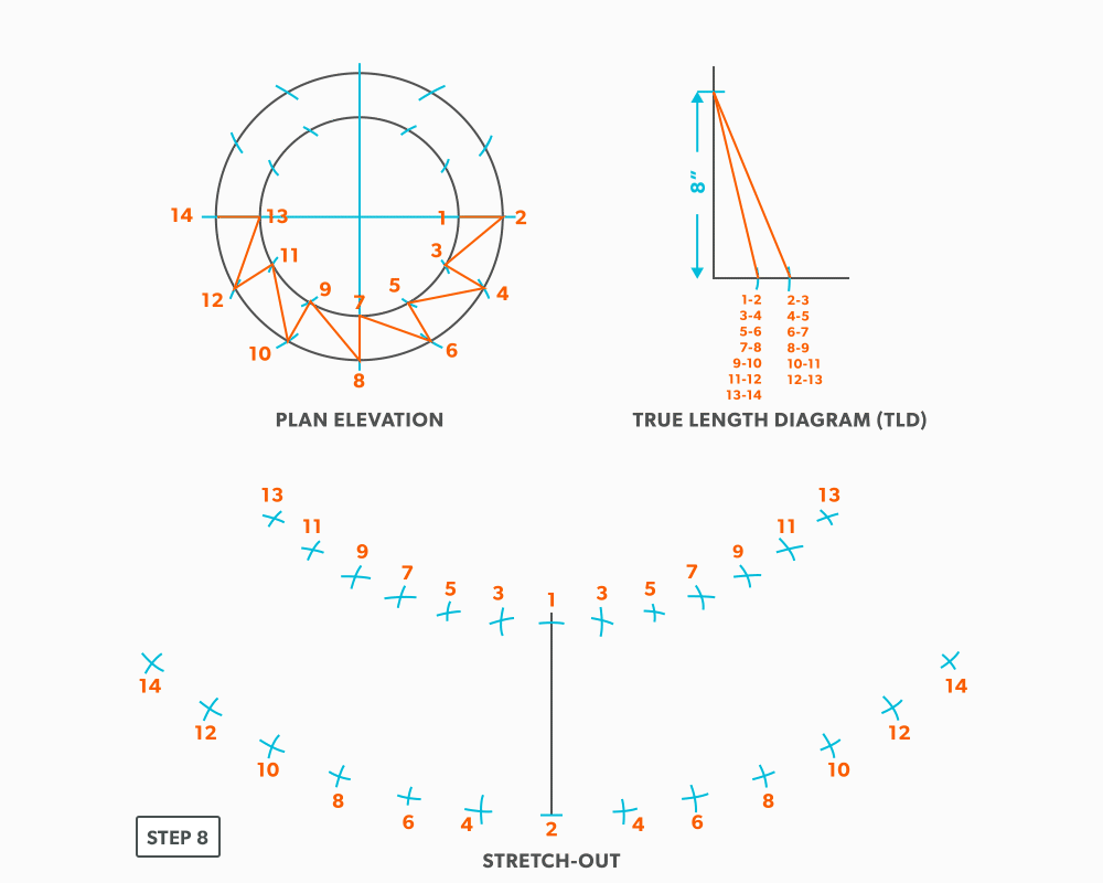
- Pick up line 3-4 from the TLD and swing it from point 3 back towards point 2.
- Pick up the step-off and swing it from point 2, to complete point 4.
- Follow this same procedures, swing a true length of an element line and a step-off to create the next point until you reach point 14.
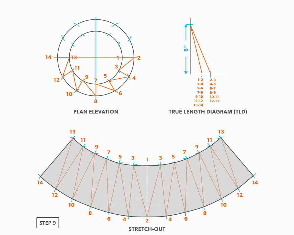
- Draw in the all the element lines and outside edges, use a flexible curve for the round ends. Because this is a fitting that could be done in radial line, although maybe not practical, the pattern will follow the same shape, having a common radius point and parallel arcs.
26
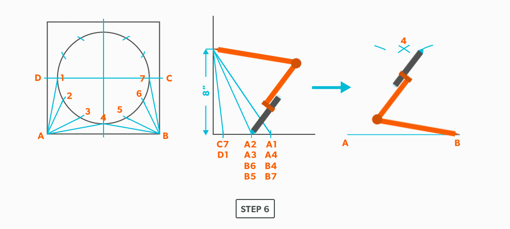
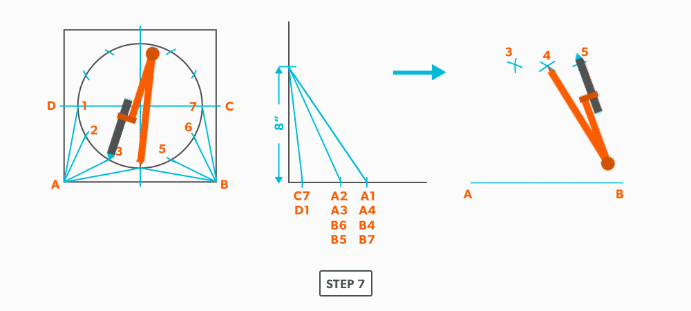
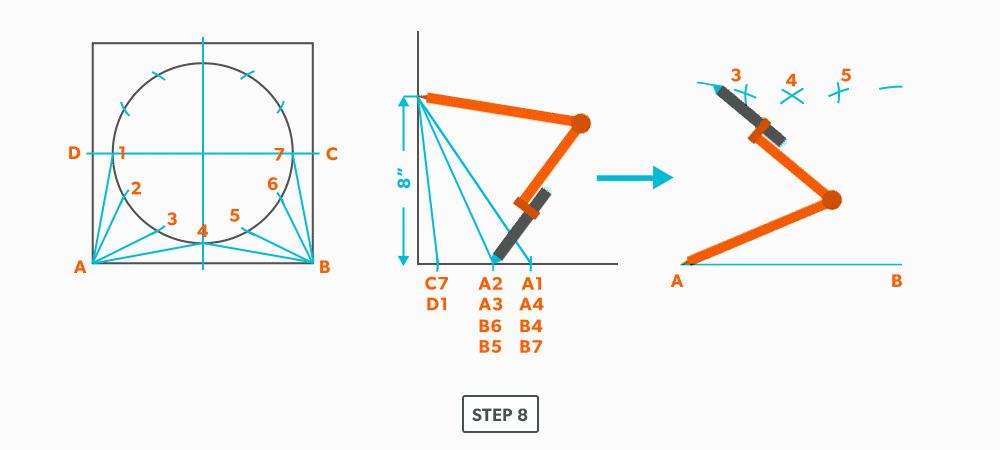
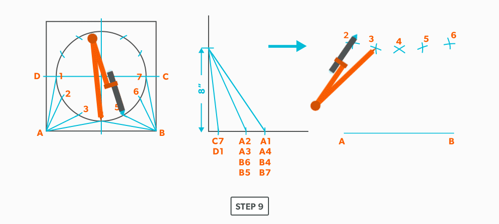
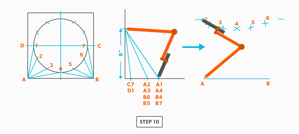
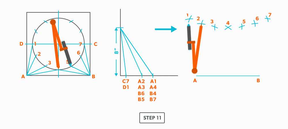
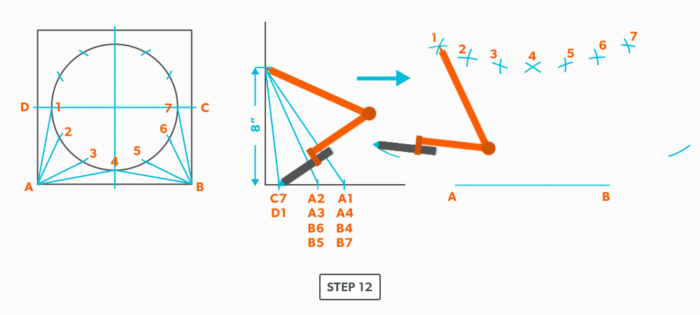
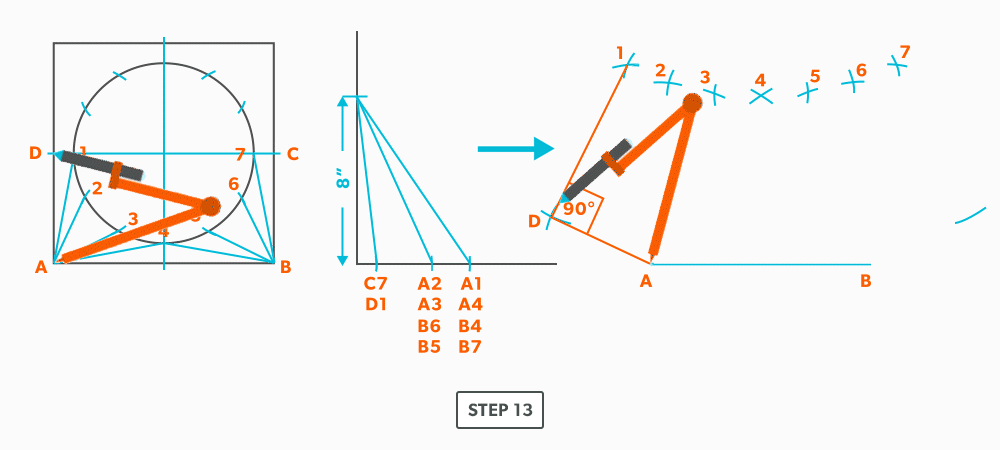
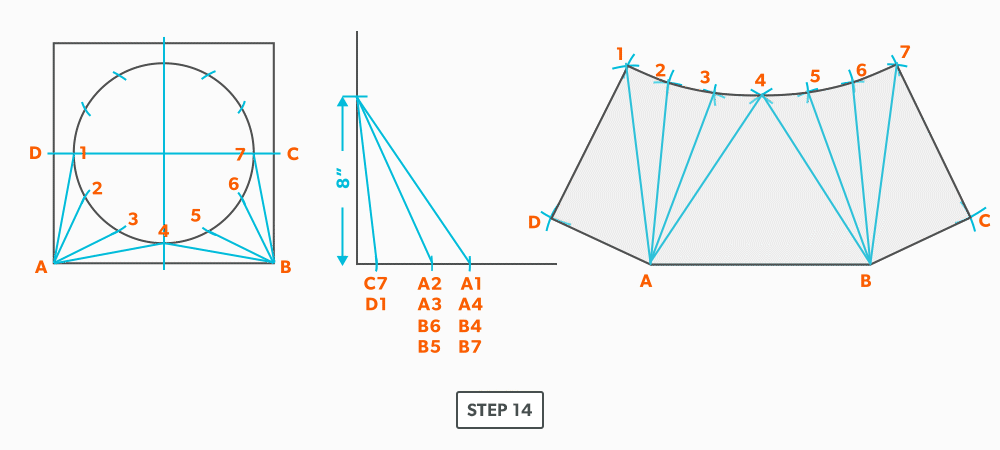
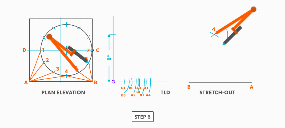
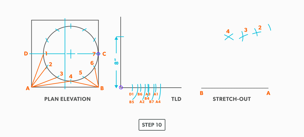
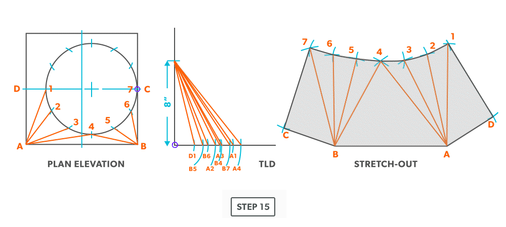
Off-Centre Square to Round
The only difference with this fitting is a few more element line lengths than an on-centre, the process is exactly the same.
- Draw a full plan view complete with all element lines and labeling. Choose a line of symmetry to place the seam so you only need to make 1 pattern. Label one half of the plan view, the round end with numbers and the square end with letters.

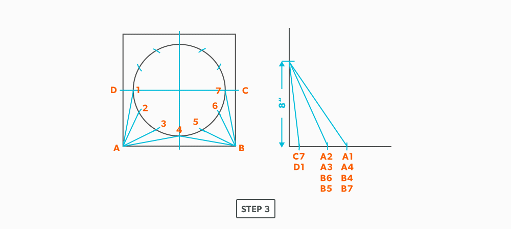
- Create a TLD and label it
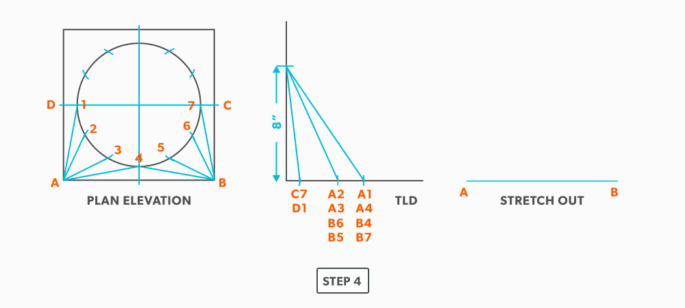
- Draw a baseline equal to line A-B.
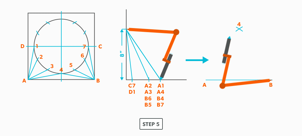
- Pick up the true length of line A-4 and swing it from point A.
- Next, pick up true length of line B-4 and swing it from point B. Where it crosses the first arc, becomes point 4.
- Pick up a step-off from the plan view and swing it from point 4. Unlike an on-centre square to round, this fitting needs to be developed one side at a time. Complete one side, then go back to finish the other side.
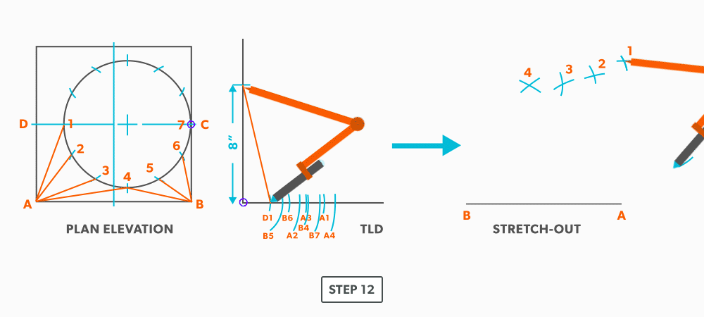
- Pick up the true length of line A-3 and swing it from point A.
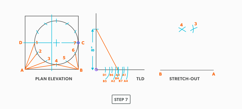
- Pick a step-off and swing it from point 3.
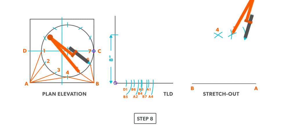
- Pick up the true length of line A-2 and swing it from point A.
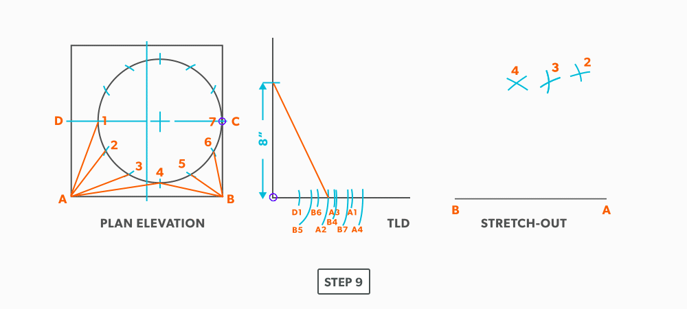
- Pick up a step-off and swing it from 2.
- Pick up the true length of line A-1 and swing it from point A.

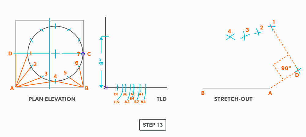
- Pick up the true length of line D-1 and swing it from 1.
- Pick up line A-D from the plan view (remember that letter to letter is true length) and swing it from point A. Remember that point D should be 90°. If it not, go back and check your work.
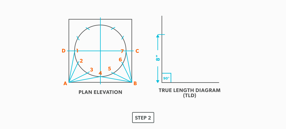
- Now, go back to point 4 and work the pattern to the other side, completing it at point C. Notice in this example, line C-7 has no length in the plan view, it is a dot. The true length is the vertical height. Zero plan length put 90 deg to the vertical height, will have no change to the vertical height.
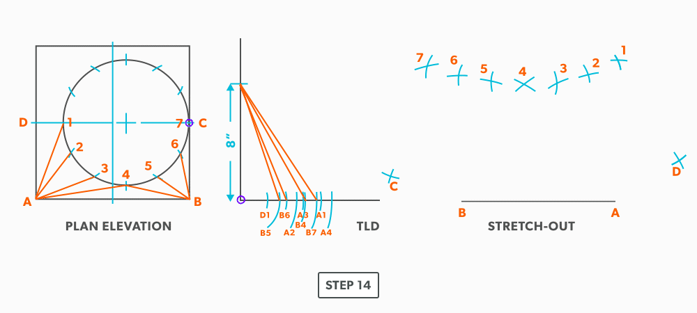
- Draw in the all the element lines and outside edges, using a flexible curve for the round end.
27
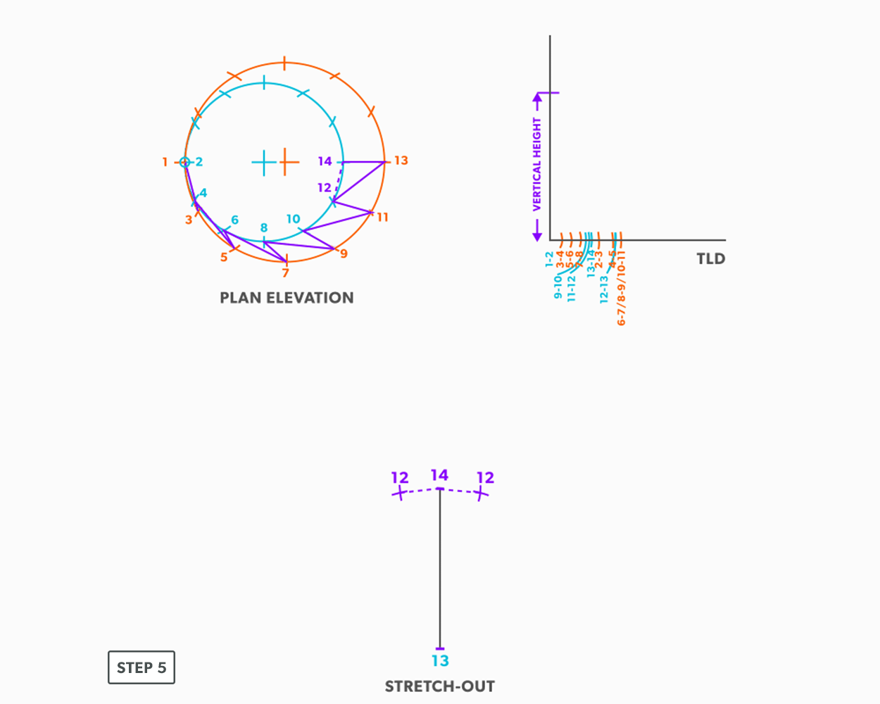
Off-Centre Round Taper
- Draw a full plan view complete with all element lines and labeling. Label one half of the plan view, go from large end to small end, zigzagging back and forth with the numbering 1-14. Remember, every round to round will be on centre one way, but it is always worth drawing the whole thing.

- Create a TLD and label all the element lines.
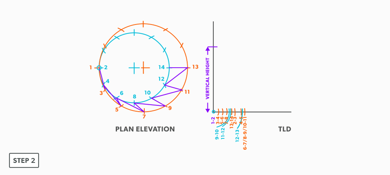
- Draw a vertical line equal to the true length of line 13-14.
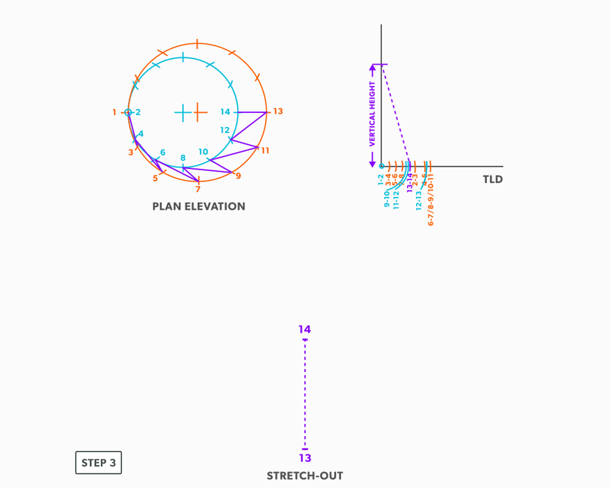
- From the TLD, pick up the true length of line 13-12 and swing it from point 13 back towards point 14. Remember to work both sides at the same time.
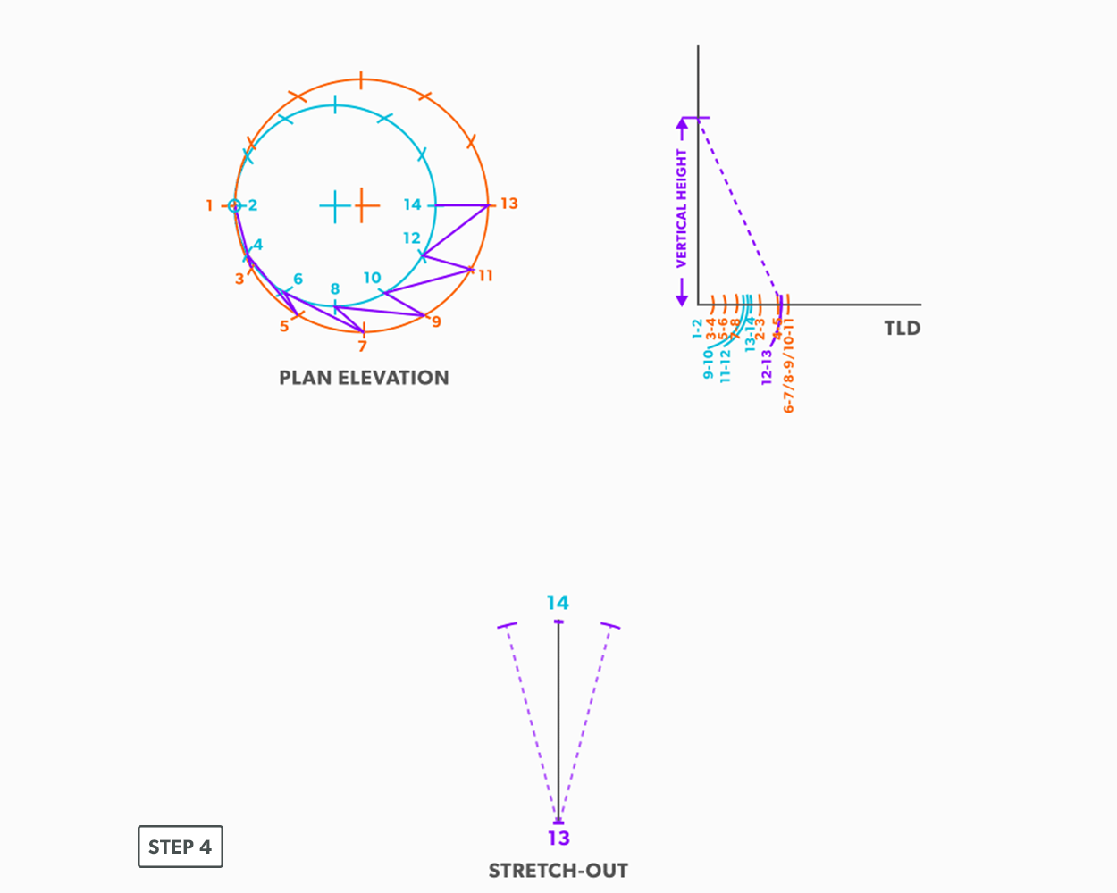
- Next, pick up step-off 14-12, and swing it from point 14.
- Pick up line 12-11 from the TLD, and swing it from point 12.
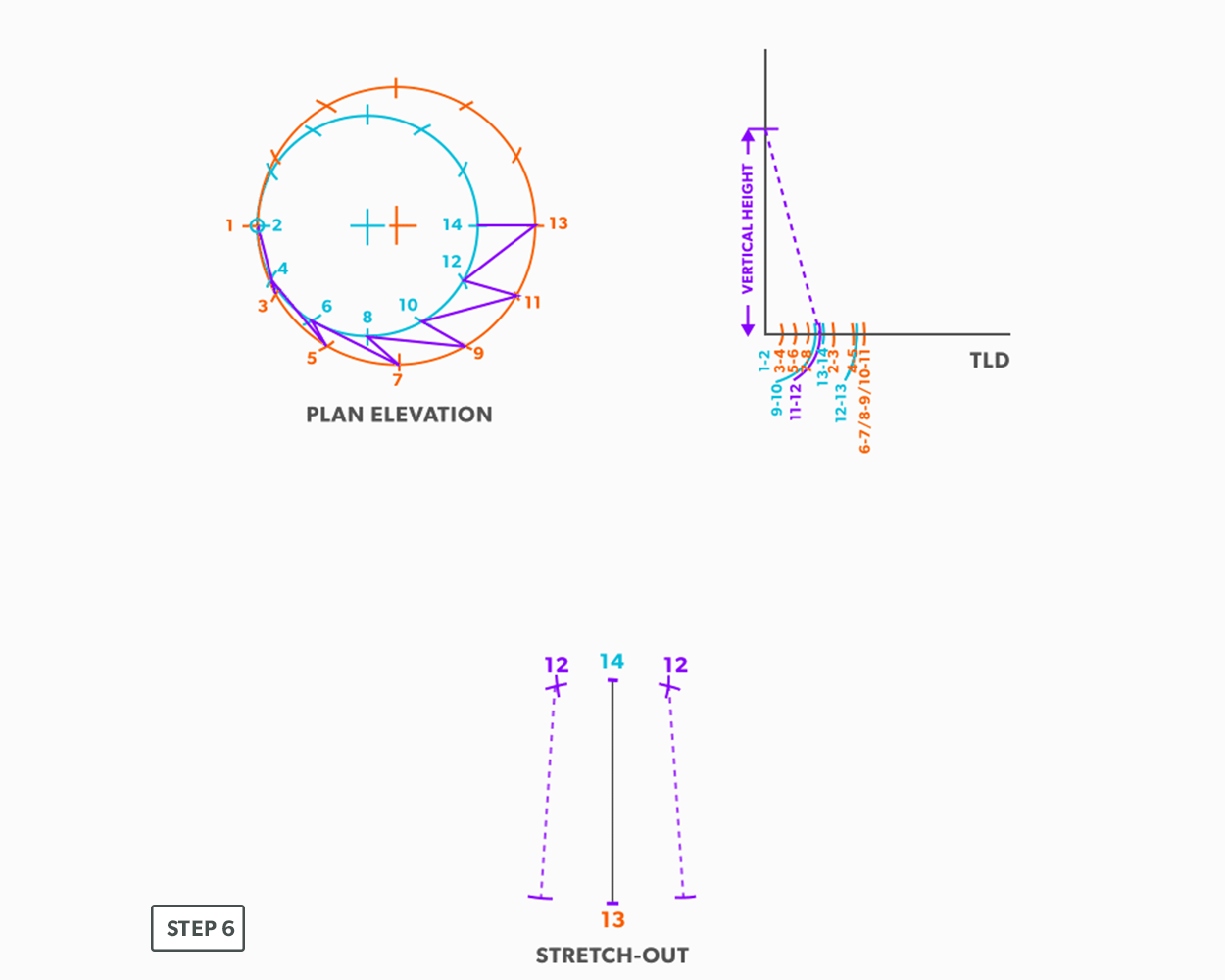
- Pick up step-off 11-13, and swing it from point 13.
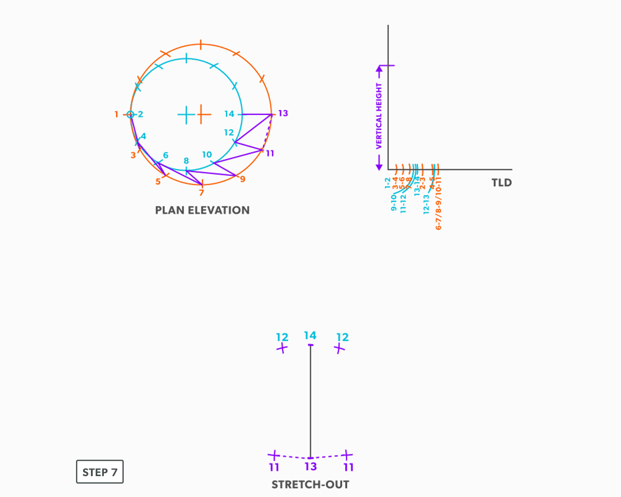
- Follow this same procedures, swing the true length of an element line and a step-off to create the next point until you reach point 1.
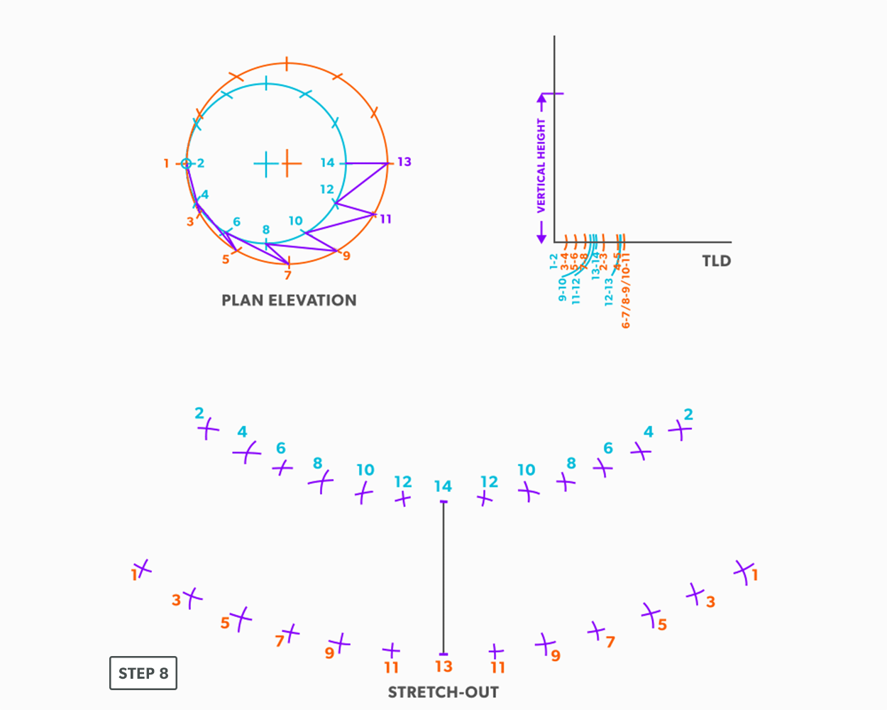
- Draw in the all the element lines and outside edges, use a flexible curve for the round ends.
28
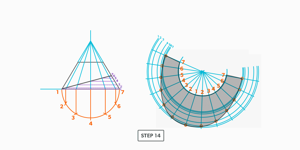
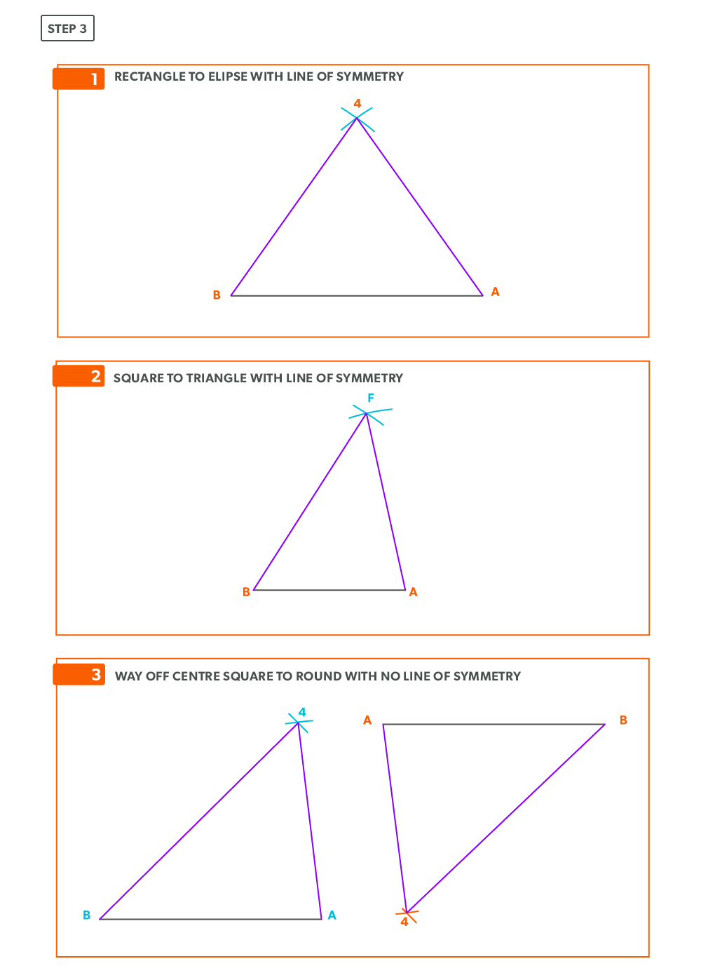
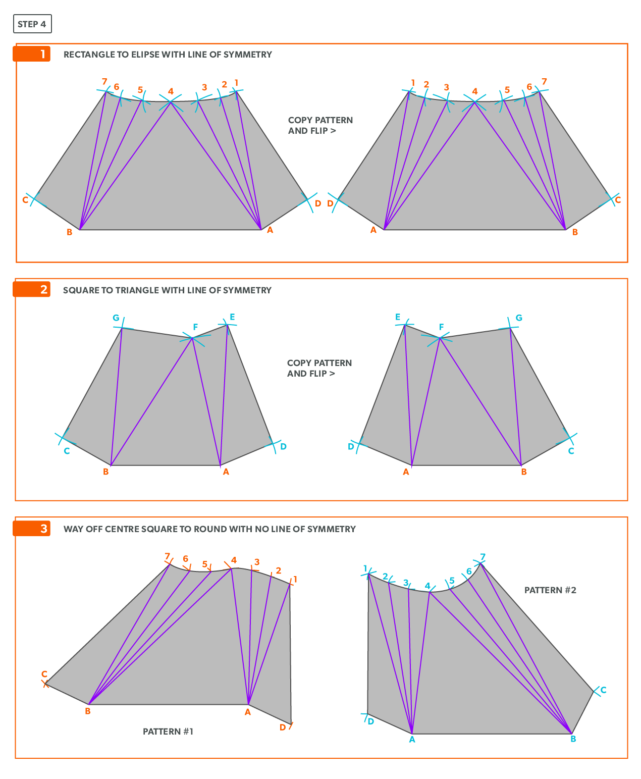
Way-Off-Centre Square to Round or Any Shape
1
Glossary
- Acute Angle/Triangle
an angle/triangle with an angle smaller than 90°
- Allowance
the material needed for a specific component-“We must allow this much extra”. Usually a seam for connection
- Apex
the intersection point of a cone, as seen in the elevation view
- Arc
a portion of a circumference
- Auxiliary Line
an extra element line added, different from the standard divisions
- Bisect
to divide in half
- Chord
a straight line from 2 points on a circumference
- Circumference
the distance around a circle, perimeter of a circle
- Diameter
the distance across a circle at center, twice the radius
- Elbow Rule
the number of pieces of a round elbow times 2 then minus 2(# of pcs x 2-2) gives us the number of gores in the elbow
- Element Line
a line representing an edge or bend
- Elevation View
looking at the front or side of something, to have elevation (height), 2D
- Frustum
a cone with the top cut parallel to the base
- Gore
a part of a round elbow which allows us to calculate the miter angle
- Horizontal
a line/plane level with the horizon. Flat, level
- Miter
an intersection of 2 pieces- an irregular cut on the end of something
- Obtuse Angle/Triangle
an angle/triangle with an angle larger than 90°
- Parallel
a line/plane that is equal distance from another
- Pattern
the shape of the object, still in 2D form
- Perpendicular
a line/plane which is 90° to another
- Plan view
looking down at something, a “birds eye view”, “floor plan” (2D)
- Point of Tangency
a straight line that touches the circle at only one point
- Profile
a half of a plan view, drawn on the outside of an object
- Quadrant
a sector which equals one quarter of the area of a circle
- Radius
the distance from center to any point of the circumference, half the diameter
- Right Angle/Triangle
an angle/triangle which has a 90° angle
- Sector
the area of a circle bound by 2 radii and an arc
- Segment
the area of a circle bound by an arc and a chord
- Slant Height (small or large)
the hypotenuse of a cone, outside edge. The slant height is always a true length in the elevation view
- Stretch-out
a shape which has been “stretched out”, to take a perimeter and make it straight
- Stretch-Out Angle/Arc
the angle or arc which encompasses a radial line pattern
- Tangent
a line which touches only 1 point of a circumference
- Triangulation from Plan View
the length of an element line, set 90° to the vertical height, gives the true length of that line
- True Length
a dimension or line that is not distorted by the view
- True Length Diagram (TLD)
a 90° corner in that we use to find the actual length of a line
- Vertex
the point at which an angle is formed
- Vertical
a line/plane straight up and down, vertically level (plumb)
2
Versioning History
This page provides a record of edits and changes made to this book since its initial publication. Whenever edits or updates are made in the text, we provide a record and description of those changes here. If the change is minor, the version number increases by 0.01. If the edits involve substantial updates, the version number increases to the next full number.
The files posted by this book always reflect the most recent version. If you find an error in this book, please fill out the Report an Error form.
| Version | Date | Change | Details |
|---|
| 1.00 | August 13, 2021 | Book published. | |